Download
1 / 23
230 likes | 397 Views
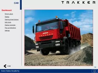
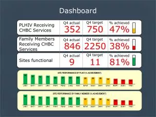
Eco Car Dashboard Display. ECE 345 Senior Design Project By Edward Wells and Darren Shea TA: Ajay Patel. Layout of Presentation . Introduction to EcoCar 2000 HEV Objective Original Design Software Overview Hardware Overview Costs and Labor Recommendations.

E N D
Eco Car Dashboard Display ECE 345 Senior Design Project By Edward Wells and Darren Shea TA: Ajay Patel
Layout of Presentation • Introduction to EcoCar 2000 HEV • Objective • Original Design • Software Overview • Hardware Overview • Costs and Labor • Recommendations
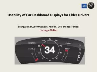
Objectives • Design display which is more suited to the EcoCar 2000 HEV • Design dashboard to work in conjunction with network and cruise control • Retrieve information from the network • Display the information on a LCD display panel
Original Design • To design dashboard display suitable for Hybrid Electric Vehicle with backlit LCD display for digital information • Pertinent information to be received from EcoCar network team via serial communications link • Original analog speedometer and tachometer dials to be retained for better visualization of changes in these values
LCD Initialization Subroutine Problems • No provided documentation • Pins and connector • LCD busy signal • Enable line • Different on-board chip
Displaying String Messages Purpose: • To become familiar with sending commands and data to the LCD display • Initial Demonstration
Speedometer LCD Output Problems • Scaling data Output = input * 0.5 Resolution • Trying to scale analog input should have been binary conversion
Tachometer LCD Output Problems • Scaling data Output = (input *3- 65)/10 • Same conclusion as speedometer output • Warning light never functioned properly, used non-scaled binary value
Analog Data Output PROBLEMS • Tried to use same control lines with inverter for both Digital to Analog Converters • In theory, should have worked, but data not latched properly • Simpler solution, use two more control lines
Delay Function • 0.587ms time delay • LCD busy signal 0.35 ms • Used delay function instead of reading LCD busy signal • Long delay(25ms) for refreshing of screen
Digital to Analog Converter • Based on DAC 0830 • Controlled by micro controller • MC1404 used for accurate reference voltage
DAC calculations Iout = (VREF/15k) x (Digital input)/255 VREF = (Iout x 15k)/( 15k x 255/256) Iout = Vout/15k Vout = 4V therefore Iout = 2.667 x 10⁻⁴ A Which gives: VREF = 4.016V So for a single step, Iout = 1.0459x10⁻⁶A Vout= 15.6882mV
Timing Diagram • Microprocessor writes to one port • Chips switched on and off corresponding to data on port • Data latched when WR goes high
Voltage to Frequency Converter • Provides pulse train for odometer driver • LF411 used as integrator for higher accuracy • Low tolerance, low thermal coefficient components, required for high accuracy
VFC Correction Circuit • Non-inverting amplifier • High gain to clean pulse train • Adjustable off set to make pulse train positive
VFC calculations Fout = (-Vin/2.09) x (Rs/Rin) x (1/RtCt) Max input voltage = -4.1V Max required frequency = 90Hz Rs = 12.1k Rin = 100k Ct = 0.01uF 90 = (4/2.09) x (12.1/100) x (1/(Rt x 0.01x10⁻⁶) Rt = 257.3k The closest value in the E12 series is 220k
Odometer Driver • CS8441 odometer driver • Frequency input • Calculates correct sequence for stepper motor
Gauge Controller • CS8190 air core gauge driver • Voltage input used instead of frequency • LF411 drives voltage into chip bypassing frequency conversion circuits
Costs & Labor Labor Typical EE entry salary $50,000/year * 1 year / 240 days * 1 day / 8 hours = $26/hour $26/hour * 2.5 * 150 hours = $9,750per person Total Labor = $19500 Parts LCD display $38 68HC11 Microcontroller $30 Resistors, Capacitors $5 DAC 0830 $ 7.08 x2 LM331 $ 8.16 LF411 $1.27 x 3 LM741 $0.46 x4 CS8190 $2.80 x 2 CS8441 $2.00 Total Parts = $108.57 Total Costs = $19,608.57
Recommendations • Wanted to interface with network and cruise control teams, display in EcoCar • Backlit LCD display • Add more functionality e.g. More warning lights, more complex LCD display