Download
1 / 5
50 likes | 222 Views
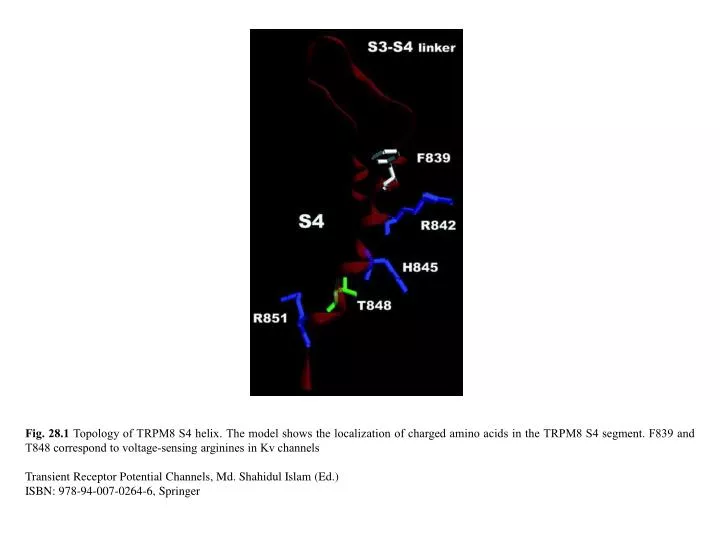
Fig. 28.1 Topology of TRPM8 S4 helix. The model shows the localization of charged amino acids in the TRPM8 S4 segment. F839 and T848 correspond to voltage-sensing arginines in Kv channels Transient Receptor Potential Channels, Md. Shahidul Islam (Ed.) ISBN: 978-94-007-0264-6, Springer.

E N D
Fig. 28.1 Topology of TRPM8 S4 helix. The model shows the localization of charged amino acids in the TRPM8 S4 segment. F839 and T848 correspond to voltage-sensing arginines in Kv channels Transient Receptor Potential Channels, Md. Shahidul Islam (Ed.) ISBN: 978-94-007-0264-6, Springer
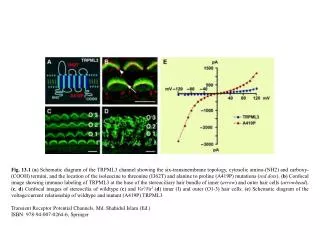
Fig. 28.2 Voltage vs normalized conductance relationships are shifted upon heating and cooling. Plots showing the normalized conductance (G/Gmax) in function of voltage (Em) at different temperatures for cells expressing TRPV1 (Left) or TRPM8 (Right). Solid lines correspond to the best fit to Boltzmann functions. The arrow indicates the direction of curve shifting upon temperature activation Transient Receptor Potential Channels, Md. Shahidul Islam (Ed.) ISBN: 978-94-007-0264-6, Springer
Fig. 28.3 TRP channels Pore Turret has been suggested as an structural part of the temperature activation mechanism. (a) An upper view of the TRPV1 pore. (b) A side view of the TRPV1 pore just showing two subunits Transient Receptor Potential Channels, Md. Shahidul Islam (Ed.) ISBN: 978-94-007-0264-6, Springer
Fig. 28.4 Allosteric models for channel activation. (a) Allosteric activation by voltage. Left,two independent equilibriums that interact allosterically. Right, when the combinations of the two equilibriums are considered, a 4-state diagram results. (b) Allosteric activation by voltage and temperature. A third equilibrium is added where RT and AT represent the resting and active conformations of the temperature sensor, respectively Transient Receptor Potential Channels, Md. Shahidul Islam (Ed.) ISBN: 978-94-007-0264-6, Springer
Fig. 28.5 Different behaviors of strict coupling versus allosteric coupling. (a) A two-states model for voltage activation (strict coupling between sensor and gate) will always have maximum P(O) =1 and minimum P(O) = 0. (b) On the other hand, with allosteric activation by voltage minimum and maximum P(O) is not restricted to 0 and 1 Transient Receptor Potential Channels, Md. Shahidul Islam (Ed.) ISBN: 978-94-007-0264-6, Springer