Download
1 / 21
210 likes | 361 Views
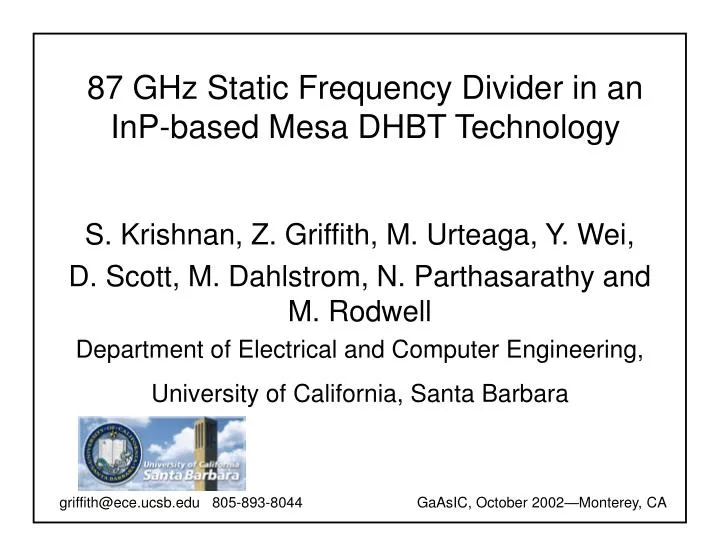
87 GHz Static Frequency Divider in an InP-based Mesa DHBT Technology. S. Krishnan, Z. Griffith, M. Urteaga, Y. Wei, D. Scott, M. Dahlstrom, N. Parthasarathy and M. Rodwell Department of Electrical and Computer Engineering, University of California, Santa Barbara.

E N D
87 GHz Static Frequency Divider in an InP-based Mesa DHBT Technology S. Krishnan, Z. Griffith, M. Urteaga, Y. Wei, D. Scott, M. Dahlstrom, N. Parthasarathy and M. Rodwell Department of Electrical and Computer Engineering, University of California, Santa Barbara griffith@ece.ucsb.edu 805-893-8044 GaAsIC, October 2002—Monterey, CA
Why Static Frequency Dividers (SFD)? MS flip-flops are very widely-used high speed digital circuits: Master-Slave Flip-Flop with inverting feedback Connection as 2:1 frequency divider provides simple test method Standard benchmark of logic speed: Performance comparisons across technologies Dynamic, super-dynamic, frequency dividers: Higher maximum frequency than true static dividers Narrow-band operation more limited applications High Speed technology performance: HRL: > 100 GHz divider—this conference with E2CL UCSB: 75 GHz static dividers using InAlAs/InGaAs TS-HBTs HRL: 72.8 GHz static dividers using InAlAs/InGaAs HBTs
Why Static Dividers, and what makes them fast MS latch: key digital element : resynchronizes data to clock often sets system maximum clock • f does not predict logic speed • fmax does not predict logic speed • Large signal operation involves switching time constants
Mesa DHBT Epitaxial Layer Structure InP Emitter n+ doped P+ InGaAs Base: 52 meV Band gap grading 2000 Å n- InP Collector
mesaIC Process: Key Features Slide 1
mesaIC Process: Key Features Slide 2
mesaIC Process: Key Features Slide 3
mesaIC Process: Key Features Slide 4
mesaIC Process: Key Features Slide 5
mesaIC Process: Key Features Slide 6
mesaIC Process: Key Features Slide 7
mesaIC Process: Key Features Slide 8
mesaIC Process: Key Features Slide complete
mesaIC Process: overview • Both junctions defined by selective wet-etch chemistry • Narrow base mesa allows for low • AC to AE ratio • Low base contact resistance— • Pd based ohmics with C < 10-7 ∙cm2 • Collector contact metal and metal ‘1’ used as interconnect metal • NiCr thin film resistors = 40 / • MIM capacitor, with SiN dielectric… -- used only for bypass capacitors • Low loss, low r = 2.7 microstrip wiring environment • Microstrip wiring environment…. • has predictable characteristic impedance • controlled-impedance interconnects within dense mixed signal IC’s • ground plane eliminates signal coupling that occurs through on-wafer gnd-return inductance
DC and RF measurements • Common emitter characteristics • Device geometry: emitter metal = 0.7 8.0 m2, real device = 0.6 ∙ 7.0 m2 • Collector to emitter area ratio, AC / AE = 4.5 • IB = 50 A per step • DC beta = 20 • Self heating present—not observed • in previous runs with same material • f = 205 GHz, fmax = 210 GHz • Measurement condition: • VCE = 1.2 Volts, Jc = 2.5 mA/m2
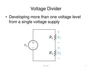
Circuit diagram: Static Frequency Divider • Circuit Details…. • ECL topology • JEF = 2.0 mA / m2 • Jsteering = 2.5 mA / m2 • VEE = - 4.5 Volts • Microstrip interconnects • Output voltage for acquire and hold components, V = 300mV • Output buffer used for measurement isolation, Vout 300 mV Hold ckt Acquire ckt
Device Count = 32 Die Area = 0.7 x 0.7 mm2 DCclk Divider Output Synthesizer clk DCbias Chip Photograph: 87 GHz Divider
DC clk Measurements: DC – 40 GHz setup 0 dm Sampling oscilloscope DC - 40 GHz Synthesizer Clk Out VEE • Clock input 0 dm • Divider Operation from 4 GHz to 40 GHz • Measurement establishes fully static nature of divider Output waveform @ 2 GHz; fclk = 4 GHz
DC - 40 GHz Synthesizer 16.67 – 25 GHz Sampling oscilloscope 0 dm Frequency tripler Clk Out DC clk 50 – 75 GHz VEE Measurements: 50 – 75 GHz setup • Clock input 0 dm • Divider Operation from 50 GHz to 75 GHz Output waveform @ 37.5 GHz; fclk = 75 GHz
DC - 40 GHz Synthesizer 20 – 40 GHz Amp DC clk Frequency tripler 75 – 110 GHz Amp Measurements: 75 – 110 GHz setup Sampling oscilloscope 9.7 dm Out Clk VEE • Clock input 9.7 dm • Divider Operation from 75 GHz to 87 GHz Output waveform @ 43.5 GHz; fclk = 87 GHz
Conclusions • Accomplishments: • Demonstrated a fully static, static frequency divider in a narrow triple-mesa DHBT process—up to 87 GHz • Future Direction: • Reduce device parasitics (rex, rbb) and wiring capacitance • Increased current density (JE) reduces • Continued lateral scaling of base contact to decrease • AE / AC ratio – lower CCB • Acknowledgements: • This work was support by the Office of Naval Research (ONR--N00014-01-1-0024) and by Walsin Lihwa / UC Core


![Frequency [GHz]](https://cdn1.slideserve.com/3024092/slide1-dt.jpg)
![Frequency [GHz]](https://cdn3.slideserve.com/6756635/slide1-dt.jpg)