Download
1 / 1
10 likes | 119 Views
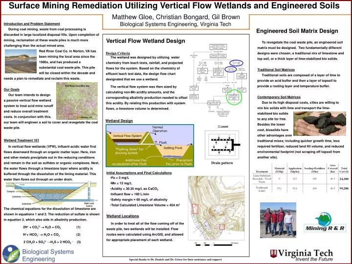
Surface Mining Remediation Utilizing Vertical Flow Wetlands and Engineered Soils. Matthew Gloe, Christian Bongard, Gil Brown Biological Systems Engineering, Virginia Tech. Introduction and Problem Statement

E N D
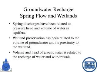
Surface Mining Remediation Utilizing Vertical Flow Wetlands and Engineered Soils Matthew Gloe, Christian Bongard, Gil Brown Biological Systems Engineering, Virginia Tech • Introduction and Problem Statement • During coal mining, waste from coal processing is discarded in large localized disposal fills. Upon completion of mining, reclamation of these waste piles is much more challenging than the actual mined area. • Red River Coal Co. in Norton, VA has • been mining the local area since the • 1980s, and has produced a • substantial coal waste pile. This pile • will be closed within the decade and needs a plan to remediate and reclaim this waste. • Our Goals • Our team intends to design • a passive vertical flow wetland • system to treat acid mine runoff • and reduce overall treatment • costs. In conjunction with this, • our team will engineer a soil to cover and revegetate the coal waste pile. • Wetland Treatment 101 • In vertical flow wetlands (VFW), influent acidic water first flows downward through an organic matter layer. Here, iron and other metals precipitate out in the reducing conditions and remain in the soil as sulfides or organic complexes. Next, the water flows through a limestone layer where acidity is buffered through the dissolution of the liming material. This water then flows out through an under drain. • The chemical equations for the dissolution of limestone are shown in equations 1 and 2. The reduction of sulfate is shown in equation 3, which also aids in alkalinity production. • 2H+ + CO32- H2O + CO2 (1) • H++ HCO3- H2O + CO2 (2) • 2 CH2O + SO42- →H2S + 2 HCO3– (3) Engineered Soil Matrix Design Vertical Flow Wetland Design To revegetate the coal waste pile, an engineered soil matrix must be designed. Two fundamentally different designs were chosen; a traditional mix of limestone and top soil, or a thick layer of lime-stabilized bio solids. Traditional Soil Matrices Traditional soils are composed of a layer of lime to provide an acid buffer and then a layer of topsoil to provide a rooting layer and temperature buffer. Contemporary Soil Matrices Due to its high disposal costs, cities are willing to mix bio solids with lime and transport the lime-stabilized bio solids to any site for free. Besides the lower cost, biosolids have other advantages over traditional mixes; including quicker growth time, less required fertilizer, reduced land fill volume, and reduced environmental footprint (not scraping off topsoil from another site). Design Criteria The wetland was designed by utilizing water chemistry from leach tests, rainfall, and projected flows for the system. Based on the chemistry of effluent leach test data, the design flow chart designated that we use a wetland. The vertical flow system was then sized by calculating non-Mn acidity amounts, and the corresponding alkalinity production needed to offset this acidity. By relating this production with system flows, a limestone volume is determined. Wetland Design Drain pattern • Initial Assumptions and Final Calculations • Fe = 3 mg/L • Mn = 12 mg/L • Acidity = 30.35 mg/L as CaCO3 • Influent flow = 190 L/min • Safety margin ≈ 60 mg/L of alkalinity • Total Calculated Limestone Volume = 454 m3 Wetland Locations In order to treat all of the flow coming off of the waste pile, two wetlands will be installed. Flow routes were calculated using ArcGIS, and allowed for appropriate placement of each wetland. Special thanks to Dr. Daniels and Dr. Grisso for their assistance and support