Download
1 / 27

E N D
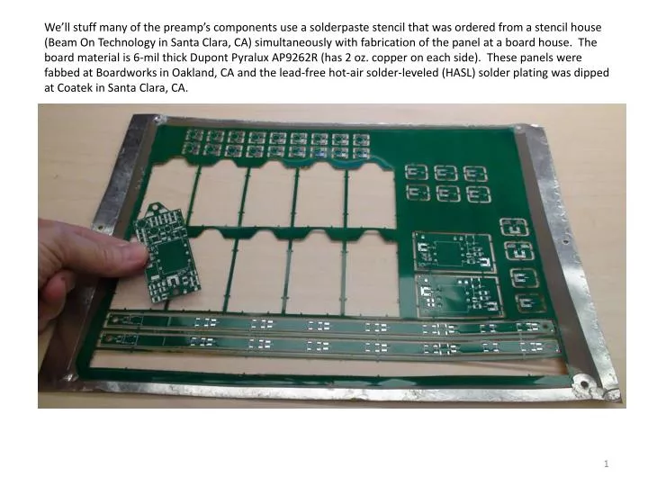
We’ll stuff many of the preamp’s components use a solderpaste stencil that was ordered from a stencil house (Beam On Technology in Santa Clara, CA) simultaneously with fabrication of the panel at a board house. The board material is 6-mil thick Dupont Pyralux AP9262R (has 2 oz. copper on each side). These panels were fabbed at Boardworks in Oakland, CA and the lead-free hot-air solder-leveled (HASL) solder plating was dipped at Coatek in Santa Clara, CA.
Snip or sand the break-out tabs after removing the board from the panel:
Beam On modified a ball-grid array stencil frame for us, as a cheaper way of applying solderpaste than a full-size stencil frame. The frame is a one-time purchase. The stencil foil and the board fixture are ordered custom from Beam On for each board design: Pastemask stencil foil Stencil frame Durostone board fixture
Kester EM828 solderpaste http://www.kester.com/products/product/EM828-Solder-Paste/
Now the solderpaste is applied to all the surface-mount pads: Next, we simply lay down the components’ leads on the pads and put the board in an oven.
A hotplate makes a good oven, as you can see the solder melt.
Once it comes up to temperature, pick up your board with tweezers and stick it all the way back in there. This lead-free solder paste needs to see 260 C:
The board only needs to be in the oven about 30 seconds. Take the board out and inspect under a stereo microscope. Touch up with a soldering iron if there are any components not completely soldered with nice fillets. Next, we need to assemble the non-magnetic socket for the preamp and solder it in...
The preamp socket blanks are not symmetric (pin 1 is 0.190” from the left edge of the preamp package, vs. 0.150” for pin 3), so be careful when assembling: 1 2 3 Note that pin 3 is unused. No need to assemble a socket pin for pin 3 into the socket blank: 6 5 4
The board layout expects the preamp’s pin 1 to go here: This socket blank is flipped around with respect to the one above it (you can see the holes aren’t aligned when the edges are. This assembled socket (notice there’s no socket pin in the pin 3 hole in the socket blank) is assembled backwards. It doesn’t fit the board layout (noticed the white socket does not match to the white outline on the board):
wrong Assemble the socket in this orientation.
The socket blanks were machined out of Delrin plastic and designed to accept these Mill-Max non-magnetic surface-mount socket cups. Use a press or staking tool to press the socket cups into 5 of the 6 holes. Skip pin 3 since since the preamp’s pin 3 is not connected to anything inside the pacakge.
The Delrin is soft and the holes are drilled for a snug fit, so you can simply push on the staking tool with your hand to press the pin in.
You can solder from the backside: 1 2 3 6 5 4 Pins 2, 5 and 6 are ground, so they are not isolated from the backside ground plane. Pin 1 is RF_in. Pin 4 is RF_out.
The preamp’s pins are too long for the socket cups, so cut them first. Also, ohm out all 5 socket pins, on the top side of the board, checking against the schematic, to ensure the correct signal trace is connected to each socket pin.
Pin 1 Done! The rest of the pads on the board are for capacitors and inductors you’ll solder in by hand during the tuning/matching process.
When you need to remove the preamp from the socket, very gently use a screwdrive on each end to pry it. Don’t touch the pins (prevent static electricity, touch something grounded first).