Download
1 / 37
440 likes | 924 Views
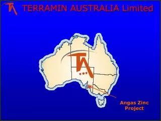
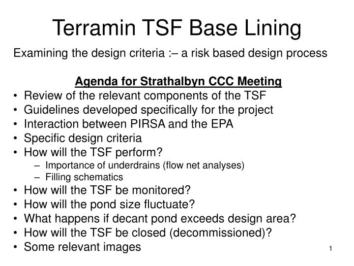
Terramin TSF Base Lining. Examining the design criteria :– a risk based design process Agenda for Strathalbyn CCC Meeting Review of the relevant components of the TSF Guidelines developed specifically for the project Interaction between PIRSA and the EPA Specific design criteria

E N D
Terramin TSF Base Lining Examining the design criteria :– a risk based design process Agenda for Strathalbyn CCC Meeting • Review of the relevant components of the TSF • Guidelines developed specifically for the project • Interaction between PIRSA and the EPA • Specific design criteria • How will the TSF perform? • Importance of underdrains (flow net analyses) • Filling schematics • How will the TSF be monitored? • How will the pond size fluctuate? • What happens if decant pond exceeds design area? • How will the TSF be closed (decommissioned)? • Some relevant images
Design guidelines were developed by PIRSA and the EPA specifically for this project Guidelines for the Management of Tailings at the Proposed Angas Zinc Project, Strathalbyn, South Australia
These design guidelines were based around the following • In view of the high potential for contamination from any discharge from this site, and the outcomes – be they real or perceived, in this environmentally important location, the environmental outcome set for the proponents to meet is: • No contamination of natural water drainage systems, ground water, land and soils either on or off site during operation and indefinitely post closure caused by mine ore or waste material. • This is intended to primarily cover surface or underground seepage containing AMD or heavy metal ions or the transport of solid waste products as a result of embankment failure, weathering or dusting.
The Evolution of the TSF Liner System • The original ATC concept design involved the conventional “best practice” earthen base. This avoids the “bath tub effect”, expedites consolidation of the tailings - and any seepage into the ground is intercepted at the site boundary and pumped back into the TSF. • The EPA advised that the regulations required that the underlying soil had to be totally protected from seepage – hence a HDPE liner was stipulated for the whole TSF and the tailings were to be thickened before discharge into the TSF. • Rather than using seepage through the subsoil to monitor for leaks, the EPA stipulated the need for a “leak detection layer” comprising a double liner where required (a fail-safe design). • It was agreed that if there was no “pressure head” on the HDPE there was no risk of a leak even with a hole in the liner and hence the issue was to establish how much of the TSF needed to be double lined
Design criteria established for ATC • The double liner to the TSF was to extend beyond the edge of the “design” decant pond to a distance of twice the width of the “design” decant pond. (With underdrains this was expected to limit the phreatic surface to within the area of the double liner – and this was to be justified by modeling) • As the decant pond will be doubling as the mine storm water pond, the “design” area was to be justified in terms of a pond size that is not likely to be exceeded more than say once a year (as determined by rainfall records).
EPA response • The EPA then applied the requirement that in the event of a storm (or whatever) that resulted in the pond exceeding the “design” boundaries, the excess water was to be removed such that the pond is reduced to the design area within seven days (this period is still under review). • The operators will be required to show how they intend to dispose of the excess water. • The approval to operate will most likely require that the infrastructure needed to expedite the removal of excess water is permanently commissioned.
Elements of the design How was the area of the “design” decant pond determined? How is the phreatic surface to be restricted to the area covered by the double liner? How will the tailings be discharged into the TSF and how will it fill? What is the decant and how will it operate? How will the maximum area of the decant be monitored? How will the tailings be prevented from polluting into the future?
Should be considering volume rather than area, but with consistent beach slopes there is a relatively consistent relationship between the two as shown below. 100 yr (ARI) event “design” pond “Mean” pond
These contours show pressure head. (10 kPa approximately equivalent to 1 m water)
Simpler to see the actual water head on the base liner and the effect and indeed vital importance of the tailings underdrains
Relevant design details The TSF has been designed to perform as simulated in the flow net analyses. A few design details are now covered
The details of the collection and monitoring system for the leak detection layer
Proposed filling sequence A series of 5 drawings have been prepared by ATC to show the extent of deposited tailings and the “design” decant pond at various stages during the life of mine. These assume that the throughput of the plant is uniform and continuous and that 100% of the tailings are directed to the TSF.
Monitoring extent of “design” pond The operating conditions set by PIRSA and the EPA will require that: The edge of the “design” decant pond does not extend beyond a distance of half the extent of the double liner. How this is to be monitored has yet to be finalised, but one concept would be to install sight boards. For example:
What happens if the decant pond exceeds the “design” area of 15,000 m2 (volume 8,000 m3)? • The 100 year ARI flood collecting on the TSF from its catchment has been estimated to add a area of water of around 38,000 m2. A volume of the order of 28,000m3 according to ATC Fig 7. • The excesswater can be removed at a rate of around 390 m3 a day using the available capacity of the decant pump. This means that if the decant pond contains say 1,000 m3 (mean area of 4,000 m2) before the flood occurs it will take about 64 days to get the decant pond back to the allowable size. • The questions are whether the phreatic surface will extend to the edge of the double liner within that time and if so – what special approved measures will have to be on hand to expedite the removal of the excess water.
The question will be how quickly the phreatic surface advances through the tailings and this is a function of the permeability of the tailings. Modelling currently under way by ATC suggests that even with the 100 yr ARI flood, that the phreatic surface will not reach the boundary of the double liner in 6 months. This however has yet to be confirmed.
The TSF will have sufficient water storage capacity at all times during its life to contain the 100 year ARI flood. 100 yr flood 30,000 m3
How will the TSF be decommissioned on closure to prevent long term contamination?
A flow net analysis has shown that leaks through the embankment liner will flow to the collection drain