Download
1 / 44
670 likes | 1.09k Views
Chemical Engineering Plant Design. Lek Wantha Lecture 02. Chemical Process Diagram.

E N D
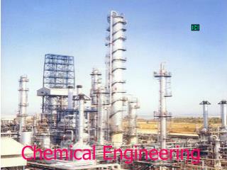
Chemical Engineering Plant Design LekWantha Lecture 02 Chemical Process Diagram
A chemist in your company’s research and development division has discovered that if he mixed two reactants in a certain proportion at an elevated temperature, he obtains a product more valuable than both reactants put together. The company contemplates manufacturing the product using a process based on this reaction. At this point the matter becomes an engineering problem or, more precisely, hundreds of engineering problems.
Engineering Problems (1) What should the reaction be carried out? What should the reactants be obtained? Should the reactor effluent, which contains the product and unconsumed reactants, be sold as is, or should the product be separated from the reactants and the latter be sent back to the reactor?
Engineering Problems (2) How should the reactants and product streams be moved to and from the reactor and any heating, cooling, and separation equipment involved in the process? Is enough known about the reaction system to be able to answer all these questions, or should additional laboratory studies be carried out? What can possible go wrong with the process, and what can be done if and when it does?
Engineering Problems (3) Are there waste products that result from the process? How much of the process should be automated, and how should it be done? How much does all of this cost? Once the plant has been built, which procedure should be followed for “startup”?
Engineering Problems (4) Six month later when startup has been achieved, why is the product not coming out the way it did in the laboratory? Is it significant or just a coincident series of bad breaks that there have been three explosions and four fires within six months in the reactor run? When the process finally starts working perfectly and the next day an order comes down to change the product specification, how can it be done without redesigning the entire process?
Block Flow Diagram (BFD) • - based on information derived from these block flow diagrams, a decision was made to proceed the process. • Process Flow Diagram (PFD) • - this included detailed process calculations. • Piping and Instrumentation Diagram (P&ID) • - this provides information needed by engineers to begin planning for the construction of the plant. The Development of a New Chemical Process
Objective (Design Specification) Collection of Data, physical properties, design methods The Design Process General of possible designs Selection and Evaluation (Optimization) Final Design
Raw material storage Stage 1 Feed preparation Stage 2 Recycle of unreacted material Anatomy of a Chemical Process Stage 3 Reaction By-products Product separation Stage 4 Product purification Wastes Stage 5 Product storage Stage 6 Sales
Basic Reaction Stoichiometry Input-Output Diagram The evolution of the principle flow diagrams in a chemical process Preliminary Process Conditions Generic Block Flow Diagram Preliminary Material Balance Block Flow Diagram (BFD) Material and Energy Balance and Equipment Specifications Process Flow Diagram (PFD) Mechanical and Instrumentation Information Piping and Instrument Diagram (P&ID)
Input-Output Diagram H2 H2, CH4 Process C7H8 C6H6 Input-output diagram for the production of Benzene
H2, CH4 Generic Block Flow Diagram H2 Feed Preparation Reaction Separation Purification C6H6 C7H8 Generic block diagram for the production of Benzene
Block Flow Process Diagram (BFPD) Block flow process diagram for the production of Benzene
Conventions and Format Recommended for Laying Out a Block Flow Process Diagram • Operations shown by blocks • Major flow lines shown with arrows giving direction of flow • Flow goes from left to right whenever possible • Light stream (gases) toward top with heavy stream (liquids and solids) toward bottom • Critical information unique to process supplied • If lines cross, then the horizontal line is continuous and the vertical line is broken. (hierarchy for all drawings in this book) • Simplified material balance provided Block Flow Process Diagram (BFPD)
Block Flow Plant Diagram (BFPD) Block flow plant diagram a Coal to Higher Alcohol Fuels Process
All the major pieces of equipment in the process will be represented on the diagram along with a description of the equipment. Each piece of equipment will have assigned a unique equipment number and a descriptive • name. • All process flow streams will be shown and identified by a number. A description of the process conditions and chemical composition of each stream will be included. These data will be displayed either directly on the PFD or • included in an accompanying flow summary table. Process Flow Diagram (PFD)
All utility streams supplied to major equipment that provides a process function will be shown. • Basic control loops, illustrating the control strategy used to operate the process during normal operations, will be shown. Process Flow Diagram (PFD)
Piping and Instrumentation Diagram (P&ID) The final control element in nearly all chemical process control loops is a valve.
Chemical engineers (or Process engineers) will design process. • Mechanical engineers and civil engineers will design and install pieces of equipment. • Instrument engineers (Electrical engineers, control engineers, ect.) will specify, install, and check control systems. • Piping engineers will develop plant layout and elevation drawing. • Project engineers will develop plant and construction schedules.
Utility flowsheet • Vessel sketches, logic ladder diagrams, wiring diagrams, site plans, structural support diagrams • Plot plans and elevation diagrams • Piping isometrics Additional Diagram
1. The PFD is divided into logical subsystems. 3D Representation of a Process
2. For each subsystem, a preliminary plot plan is created. 3D Representation of a Process Grade-Mounted Horizontal Inline Arrangement
2. For each subsystem, a preliminary plot plan is created. Structure-Mounted Vertical Arrangement 3D Representation of a Process
2. For each subsystem, a preliminary plot plan is created. 3D Representation of a Process
2. For each subsystem, a preliminary plot plan is created. 3D Representation of a Process
3. The elevation of all major equipment is established. 3D Representation of a Process
3. The elevation of all major equipment is established. 3D Representation of a Process
4. Major process and utility piping are sketched in. • The final step in this preliminary plant layout is to sketch in where the major process (and utility) pipes (lines) go. 3D Representation of a Process