Download
1 / 41
410 likes | 587 Views
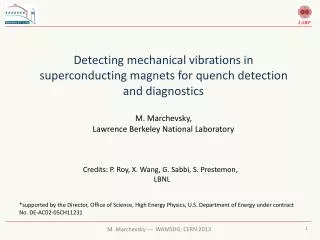
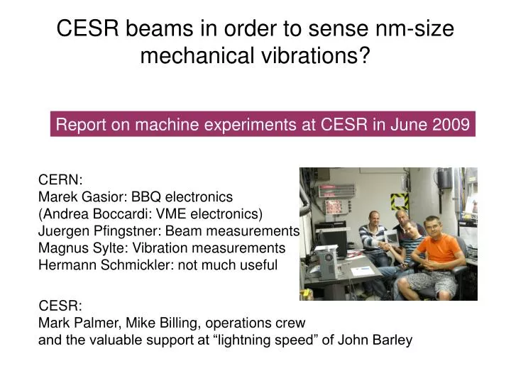
CESR beams in order to sense nm-size mechanical vibrations?. CERN: Marek Gasior: BBQ electronics (Andrea Boccardi: VME electronics) Juergen Pfingstner: Beam measurements Magnus Sylte: Vibration measurements Hermann Schmickler: not much useful

E N D
CESR beams in order to sense nm-size mechanical vibrations? CERN: Marek Gasior: BBQ electronics(Andrea Boccardi: VME electronics)Juergen Pfingstner: Beam measurementsMagnus Sylte: Vibration measurementsHermann Schmickler: not much useful CESR: Mark Palmer, Mike Billing, operations crewand the valuable support at “lightning speed” of John Barley Report on machine experiments at CESR in June 2009
Outline • Motivation • Experimental Set-up • First results- amplitude calibration- residual beam motion- noise of detection system • Conclusions and Perspective
CLIC stabilization requirements • Mechanical stabilization requirements: Quadrupole magnetic axis vibration tolerances: • Main beam quadrupoles to be mechanically stabilized: • A total of about 4000 main beam quadrupoles • 4 types • Magnetic length from 350 mm to 1850 mm
Present design approach(CLIC stabilization WG, C.Hauviller et al.) • Mechanical active stabilization in a feedback loop using electromechanical sensors and (piezo) actuators • Optimized mechanical design for- girders, magnets and electromechanical alignment system- best choice for number and position of actuators and sensors- low Q mechanical resonances in order to avoid vibration amplification- mechanical resonances at the highest possible frequencies • Mimimization of environmental noisethrough isolation from vacuum chamber vibration, coolent flows, cable vibration and microphonic coupling • Experimental verification of the result of stabilization:- construction of real hardware based on a quadrupole prototype, an active stabilization system Present work program: A type 4 quad ready for lab tests mid 2010.
Main Beam Mock-up Work launched within the collaboration • Functionalities • Demonstrate stabilization in operation: • Magnet powered, Cooling operating • Configurations • 1- Stand-alone • 2- Integrated in Module • 3- Interconnected • Accelerator environment • Parts / Measuring devices • Floor (damping material) • Support • Pre-alignment • Stabilization • Magnet • Vacuum chamber and BPM • Independent measurement Slide taken from C.Hauviller, ACE 2009
Main beam quadrupole • Under final design. • Plain material (incompatible with corrector magnet) • Assembly methods to be tested (accuracy of some microns!) Slide taken from C.Hauviller, ACE 2009
Necessary complementary verification ? • The demonstration of the stabilization of the magnet (=Magnetic field?) is based on “zero” signals of electromechanical sensors on the outer shell of the magnet. • The physical size of the sensors do not allow to mount them close to the pole tips or inside the magnet. • Pole tip vibrations, coil vibrations might exist without the outer monitors measuring them. • The limited number of monitors might not catch all vibrations. Question:can another physical process be used to verify the stability of the magnetic field? try a high energetic low emittance particle beam
Standard Quad Standard Quad Standard Quad Standard Quad Standard Quad Standard Quad Stabilized Quad High sensitivity BPM Calibrated mechanical exciter Validation of Quad stabilization principle (1/2)
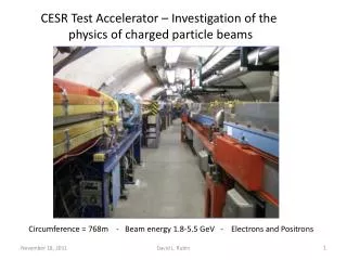
Validation of Quad stabilization principle (2/2) • insert a CLIC quadrupole (fully integrated into a CLIC module with a mechanical simulation of the environmental noise) into an electron synchrotron • in frequency bands in which the intrinsic motion of the particle beam is smaller than 1nm, observe the effect of quad stabilization on/off • in frequency bands, where the particle beam moves more than 1nm, the beam validation is limited to exciting mechanical vibrations of the quad at larger amplitudes and measuring the gain of the feedback. The performance of the feedback system at lower amplitudes would in this case to be estimated from the signal to noise ratio of the actuators and sensors. objective of the test experiment at CESR-TA:- what is the rms of the residual eigen-motion of the CESR beam as a function of frequency- what are the limits in noise performance of the BPM electronics?
experimental set-up • Excitation of beam with a vertical orbit corrector dipole,direct connection to dipole coil (Q10W) • Observation of beam oscillations on vertical pickups with modified BBQ electronics (Q8W) heavy downsampling in special acquisition cards, up to 17 minutes measurement time. • Calibration of the system using a 300 um peak-peak oscillation measured in parallel with BBQ system and local orbit system. • Various beam conditions, partial shutdown of injector complex etc… • 4 measurement shifts • Very friendly and effective support by CESR team
Data processing VME crate with DABs NIM crate down sampling factor 1 to 256 DAQ 6 ch. DAC sine wave generation FFT Ground motion meas. ADC sown sampling factor 4 6 ch. • Data transfer and • Control of DABs and • DAQs USB • DAC and ADC • sampling rate: 44kS/sec • resolution 24 Bit • FFT: • Length: 64kS • no windowing • 22 FFTs are averaged (measurement time >1000sec) LabView program Storage Display Laptop (Windows XP) In CTF3 this measurement would take about 100 days
VME-crate with DAB cards Digitizers
Getting BPM resolutions below the nm • Aperture of BPM approx. 50 mm or more • Wide band electronics thermal noise limit: 10^-5 of aperture • Narrow band front-end gains factor 10…100 • State of the art commercial BPM system (“Libera Brilliance”)reaches 5nm/sqrt(Hz), i.e. with 1000 s measurement time 150 pm rms noise. • Different approach:BBQ electronics: “Zoom in” getting high sensitivity for beam oscillations, but loosing absolute information of DC = closed orbit information.
Direct Diode Detection (3D) – the principle • Peak detection of position pick-up electrode signals (“collecting just the cream”) • fr content converted to the DC and removed by series capacitors • beam modulation moved to a low frequency range (as after the diodes modulation is on much longer pulses) • A GHz range before the diodes, after the diodes processing in the kHz range • Works with any position pick-up • Large sensitivity • Impossible to saturate (large fr suppression already at the detectors + large dynamic range) • Low frequency operation after the diodes • High resolution ADCs available • Signal conditioning / processing is easy (powerful components for low frequencies)
=100T 4 bunches = 100 T Direct Diode Detection – The principle Signals of both peak detectors Detector signal difference =0, = 0.01 q=0.1, Cf =Cpu =T
Architecture of the Base Band Q (BBQ) Measurement System Detector box (for one PU electrode) Analog front-end box (2 channels) • For CESRTA the system bandwidth is 10 Hz – 5 kHz
Amplitude calibration • The BBQ electronics does not have a good absolute calibration for the measurement of absolute beam oscillation amplitudes. • On the contrary the BBQ electronics is linear over many decades and frequency independent within the bandwidth given by the electronic filters. • Disconnect orbit steerer from control system and get two wires for own excitation… • 1st attempt of calibration: DC mode: inject 1 A ( lab current source)of DC current into steerer magnet, measure (calculate) orbit displacement at BBQ-pickup and use this relation for future low current AC excitations.Done, but problem is unknown bandwidth of magnet and vacuum chamber • 2nd attempt: AC-mode: inject AC modulation (0.5 A rms) at various frequencies and measure resulting orbit oscillation with BPM system.(For 0.5 A we had to borrow a HiFi amplifier and we just managed to be above the sensitivity of the turn by turn CESR orbit system:0.5 A at 20 Hz gave a 300 +-30 um peak-peak orbit oscillation.
Calibration DC AC Preliminary “fit by eye”; data of this calibration (CESR BPM rawdata) on a file on a website, which is presently not accessible to us - 1 mm at Q8W
Amplitude Calibration Measured in parallel with turn by turn orbit system: measured amplitude: 300 um pp ~ 100 um rms
Simultaneous excitation with 6 different tones @ 17.2 mA rms each
Continous Calibration • In the end we decided to leave a continuous 20 Hz excitation of 20 mA as reference excitation through all measurements. • This corresponds to a beam oscillation of about 4 um rms at 20 Hz.
4 um reference tone @ 20 Hz 1 nm line
18 pm in 47 s measurement time = 0.12 nm/sqrt(Hz) Noise evaluation 40 pm Ratio: 4,92 <-> sqrt 22 = 4,69 Compare to Libera Brillance with 0.25 um @ 2KHz = 5nm/sqrt(Hz)
Is all we measure beam motion? There is more signal with the synchrotron off What is this pedestal?
PM to AM demodulation of Rf-noise • With the BBQ detection principle the system is sensitive to hase jitter of the RF, i.e. jitter of the revolution time.
Vibration Sensors, Setup 1 Quadrupole Q8W Geophones Sensitivity: 2000 V/(m/s) Frequency range: 1/30 – 80 Hz Accelerometers Sensitivity: 1 V/(m/s^2) Frequency range: 0,1 – 200 Hz 18/06/2009 Mechanical Measurement Lab Magnus Sylte EDMS 1004462
Acquisition System and Analysis Parameters Version:MKII Max sampling frequency: 384 KHz A/D converter: 24 bit Dynamic range: 10mV-50V Analysis Parameters: Measurement length: 1024s and 1440s Window: Hanning Sampling rate: 1024Hz Block length: 64s Average: Linear Overlap: 66,7% 18/06/2009 Mechanical Measurement Lab Magnus Sylte EDMS 1004462
Average Spectra on ground and on top of quadrupole compared to beam motion Average FFT Geophones Average FFT BPM Ground Vibration Quadrupole Vibration 18/06/2009 Mechanical Measurement Lab Magnus Sylte EDMS 1004462
Quad (black) Beam Does not really fit, but there are more than 100 quads on different supports…
First vertical bending modes Transfer function Coherence Phase 18/06/2009 Mechanical Measurement Lab Magnus Sylte EDMS 1004462
First lateral bending mode Transfer function Coherence Phase 18/06/2009 Mechanical Measurement Lab Magnus Sylte EDMS 1004462
Vibration Sensors, Setup 2 Accelerometer 2 Accelerometer 1 08/07/2009 Mechanical Measurement Lab Magnus Sylte EDMS 1004462
Accelerometer 1 Accelerometer 1 Geophone on the floor Average FFT 08/07/2009 Mechanical Measurement Lab Magnus Sylte EDMS 1004462
Accelerometer 2 Accelerometer 2 Geophone on the floor Average FFT 08/07/2009 Mechanical Measurement Lab Magnus Sylte EDMS 1004462
Side product:modified BBQ electronic with higher bandwidth:perfect tune-monitor with 60 db signal/noise ratio
Perspectives for the future 1 nm line Feedback Off Feedback ON
Conclusions and Perspectives (1/2) • An electron beam (tens of um beam size) can be used to sense disturbances (vibrations) down to the sub-nm level- using an optimized BBQ electronics- using about 10^9 samples in 17 minutes measurement time • At CESR-TA the accelerator itself has disturbances that add up to - smaller values than 1 nm rms above 80 Hz- to much larger values below 80 Hz • We need to clarify what fraction of this is PM-AM demodulation of RF-phase jitter • Hence in the interesting region 10 Hz – 100 Hz no full demonstration of the stability of a CLIC quadrupole proto-type can be made,but:- in this frequency range the gain of a stabilization loop can be measured at 10-100nm levels- a special optics can be designed in order to get higher sensitivity using the amplification of the lattice. • Due to its availability CESR-TA stays interesting as CLIC test-bed
Conclusions and Perspectives (2/2) • Other European light-sources have been contacted(Diamond, Soleil, PSI, ESRF, PetraIII) for similar experiment. so far no “enthusiasm” to install a new quadrupole into their machine PSI will receive us in late autumn for the same measurementand proposes to stabilize an existing SLS quadrupole • CESR-TA would hopefully except to have a CLIC quad installed limited experimental program at low frequencies (for all machines): not the real CLIC quad: higher aperture, lower strength… still a lot of information to be gained by these experiments • Presently we study the CESR optics in order to calculate the amplitude factor between quad motion and visible amplitude in the BPM.This factor can be much bigger than 1! • Such an experience is only possible at all due to a major improvement in BPM sensitivity for beam oscillations from 5 nm/sqrt(Hz) (Libera Brillance) to 0,12 nm/sqrt(Hz) (BBQ) • Several details of BBQ noise performance, frequency dependence, beam current dependence and dependence of beam emittance to be measured