Download
1 / 52
520 likes | 549 Views
Explore the importance of Statecharts in modeling dynamic behaviors of objects in UML development. Learn about Finite State Machines and Statechart elements with examples.

E N D
UML Diagrams:StateChartsThe Dynamic Analysis Model Instructor: Dr. Hany H. Ammar Dept. of Computer Science and Electrical Engineering, WVU
outline • UML Development - Overview • The Requirements Model and the Analysis model • The Analysis Model and the importance Statecharts • Finite State Machines and Statecharts • More on State Chart Elements • Examples
SCENARIOS ACTORS USE CASES UML Development - Overview REQUIREMENTS ELICITATION Time D Requirements Engineering System/Object SEQUENCE DIAGRAMS A T A ANALYSIS CLASS DIAGRAM(S) StateChart DIAGRAMs ANALYSIS Specify Domain Objects D I OPERATION CONTRACTS C T Architectural Design Include Design Objects I SUBSYSTEM CLASS/ OR COMPONENT DIAGRAMS DESIGN SEQUENCE DIAG. DEPLOYMENT DIAGRAM O N DESIGN DIAGRAMS A R Detailed DESIGN Y Object Design IMPLEMENTATION CHOICES IMPLEMENTATION Activity DIAGRAMS IMPLEMENTATION PROGRAM
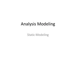
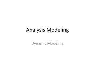
The Requirements Model and the Analysis Model Requirements Elicitation Process Functional/ Nonfunctional Requirements Use Case Diagrams/ Sequence Diagrams (the system level) The Analysis Process Static Analysis Dynamic Analysis - Class Diagrams - State Chart Diagrams/ Refined Sequence Diagrams (The object level)
outline • UML Development - Overview • The Requirements Model and the Analysis model • The Analysis Model and the importance Statecharts • Finite State Machines and Statecharts • StateChart Elements • Examples
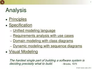
The Analysis Model and the Importance of StateCharts • StateCharts are particularly important for real-time systems, • Control functions are typically activated at specific states of the system • StateCharts model the dynamic behavior of an object (with multiple states of behavior) by showing the possible states that the object can be in (idle, busy, waiting for selection, timedout, processing_transactions, etc) • In the analysis model a StateChart diagram is needed for each class of domain objects (including the system class) defined in the class diagram that has multiple states of behavior.
Example: StateChart for the ATMControl class What are the limitations of this Diagram?
outline • UML Development - Overview • The Requirements Model and the Analysis model • The Analysis Model and the importance Statecharts • Finite State Machines and Statecharts • StateChart Elements • Examples
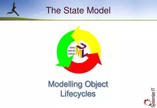
Finite State Machines and Statecharts • Statechart Graphical representation of finite state machine–States are rounded boxes–Transitions are arcs • Statechart relates events and states of a class of objects •Event –Causes change of state Referred to as state transition •State –A recognizable situation –Exists over an interval of time–Represents an interval between successive events
Finite State Machines (FSMs) and StateCharts (SCs) • SCs are graphical representation of FSMs • They can depict complex FSMs consisting of a hierarchy of state diagrams • SCs consist of states and transitions • A state depicts an actual state of behavior that an object can be in during its life time • A transition from one state to another is caused by an event (e.g., user input, received a message from another object, etc)
StateChart RulesStates of an Object • A recognizable situation • Exists over an interval of time • Represents an interval between successive events • Can be a Macro state or a Micro state • A Macro State is defined by another StateChart containing Macro and Micro states • A Micro state is a primitive state not defined any Further
The History mark means subsequent entries are to the last active state
outline • UML Development - Overview • The Requirements Model and the Analysis model • The Analysis Model and the importance Statecharts • Finite State Machines and Statecharts • More on State Chart Elements • Events, Conditions, Actions, and Activities • Examples
Events • Event–A discrete signal that happens at a point in time –Also known as a stimulus –Has no duration •Two events –May logically depend on each other –E.g, ATM Card inserted before Pin # entered •Two events –May be independent of each other (they can occur independently) –E.g., Cancel
Events and Conditions • State transition label – Event [Condition] • Condition is a Boolean function – Conditions are optional on statecharts – Condition is true for finite period of time • When event occurs, condition must be true for state transition to occur.
Actions • Can be defined as state transition label –Event / action(s) –Event [condition] / action(s) • Actions –Executed as a result of state transition –Executes instantaneously at state transition –Terminates itself • Entry Actions • Defined for a given state and executes on entry to this state from any state • Exit Actions • Defined for a given state and executes on exit from this state to any state
Example: Entry Actions, execute on the entry to a state after a state transition
Activities • Activity –Executes for duration of state •Enable Activity on entry to state •Disable Activity on exit from state • Examples of activities –Increase Speed •Executes for duration of Accelerating state –Maintain Speed •Executes for duration of Cruising state –Resume Cruising •Executes for duration of Resuming state
outline • UML Development - Overview • The Requirements Model and the Analysis model • The Analysis Model and the importance Statecharts • Finite State Machines and Statecharts • StateChart Elements • Examples
Incomplete Statechart and incorrect state label Why?
Example: Digital Sound RecorderUser Interface subsystem Design Class diagram
Example: Digital Sound RecorderStateChart of MenuUserMode class
Example: StateChart for the ATMControl class What are the limitations of this Diagram?
Example: Macro States, Hierarchical StateCharts ATM system
Example: Auto Cruise Control and Monitoring (The Cruise Cont. Subsys)
Example: Elevator Control Collaboration Diagram Door: Door Display: Display 7: Door_Closed=TRUE 11:Door_Closed=TRUE Floor_No_Arrived 6: Open_Door 10:Open_Door 1: state “Idle”, Floor_No_Arrived=1 3: state “Going_Up”, Req_Highest_Floor=7 4: state “Passenger_Loading”, Floor_No_Arrived=7 8: state “Going_Down”, Req_Lowest_Floor=5 9: state “Passenger_Loading”, Floor_No_Arrived=5 12: state “Idle”, Floor_No_Arrived=5 5: Req_Floor=5 Inside_Elevator_Buttons: Inside_Elevator_Buttons Elevator_SW_Sys: Elevator_SW_Sys 2: Req_Floor=7 Floor_No_Arrived Floor_Sensor: Floor_Sensor Central_Station: Central_Station
Scenario of the Collaboration Diagram • Idle on Floor 1 • Gets request from Floor 7 • Going Up to Floor 7 • Gets request from inside passenger to Floor 5 • Loading on Floor 7 • Going Down to Floor 5 • Loading on Floor 5 • Idle on Floor 5
In_Service Req_Floor=NULL Elevator_SW_Sys State Diagram Idle Floor_No_Arrived=Req_Floor /Open_Door Passenger_Loading Alarm is off Floor_No_Arrived= Req_Floor /Open_Door Req_Floor!= NULL Floor_No_Arrived > Req_Lowest_Floor && Door-Closed=TRUE Floor_No_Arrived < Req_Highest_Floor && Door-Closed=TRUE Out_of_Service Floor_No_Arrived< Req_Floor Floor_No_Arrived= Req_Floor /Open_Door Floor_No_Arrived> Req_Floor Alarm is on Going_Up Going_Down Floor_No_Arrived < Req_Highest_Floor && Floor_No_Arrived != Req_Floor Floor_No_Arrived > Req_Lowest_Floor && Floor_No_Arrived != Req_Floor