Download
1 / 67
670 likes | 836 Views
Present Status of Shanghai Light Source (SSRF). Dekang LIU 2004/12/8. A. Status of SSRF. Overview of the project progress SSRF Design Optimization Project Budget and Schedule. B. Status of I & C for SSRF * Status of Control System

E N D
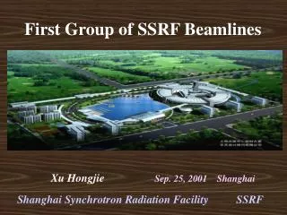
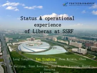
Present Status of Shanghai Light Source (SSRF) Dekang LIU 2004/12/8
A. Status of SSRF • Overview of the project progress • SSRF Design Optimization • Project Budget and Schedule B. Status of I & C for SSRF * Status of Control System * Status of Instrumentation
TheSSRF project proposal was officially approved by the Chinese central government in January 2004!
SSRF (Shanghai Synchrotron Radiation Facility): An intermediate energy 3rd generation light source; • The SSRF will be located in ShanghaiZhang-Jiang High Tech Park (Pudong new development district); • The SSRF site occupies a area of 600m300m • About 25km from Pudong international airport • Close to Subway and magnetic leveled train line • Convenient to access the Shanghai down town area
BEPCII/IHEP Spring-8 PLS PF Hefei LS TLS INDUSII SSRF/SINAP
Site of SSRF Pudong Airport Hongjiao Airport Magnetic leveled train 35Km/7minits 430km/h Max
Layout of SSRF 600m 300m
Brief History of the SSRF Project • Dec.1993: Three Chinese scientists proposed formally to central government to build a third generation light source; • March 1995: The Chinese Academy of Sciences and the Shanghai municipal government made a joint proposal to construct the SSRF in Shanghai; • June 1997 and March 1998:The state science and technology leading group and the state planning committee approved the SSRF R&D program; • Jan.1999~March, 2001: The SSRF R&D with budget of 80M Yuan was being performed; • Jan. 2004: The SSRF project was finally approved
About 10 year’s efforts to get this light source project approved; • There are still one more project steps before performing the groundbreaking this year; • Project feasibility study report review approval At July of 2004 • Project detailed design study report review and approval
Hardware Prototype in Pre-R/D (1999-2001) Bending Magnet (made in IHEP, Beijing)
Quadrupole Magnet Sextupole Magnet (Made in Kelin, Shanghai) Made in CUSTC, Hefei
Bending Magnet Power Supply 500A/100V, 1105/24hrs
Kicker Magnet and Its Pulser 4s half-sine-wave 0.12T peak field jitter time < 6.5ns
High Power RF System 500MHz, 180kW CW RF local control station
BPM And Its Mapping System 2m resolution Timing System
Evolution of the SSRF Designs • There have been 4 main SSRF design versions since 1996, and the SSRF has been evolved to a high performance and cost-effective light source for the past 8 years, which includes: • Upgraded the SSRF storage ring energy from 2.2 GeV to 3.5 GeV; • Optimized the storage ring with high flexibility, low emittance and high beam orbit stability; • Optimized the SSRF complex operating with top-up injection modes; • …
1996 1998 2001 2003
SSRF Accelerator complex • 100MeV Electron Linac • 3.5GeV Booster • 3.5GeV Storage Ring • Beam Line and Experimental stations
Latest SSRF Design Optimization • Optimization to enhance the SSRF capability and cost-effectiveness • lower emittance and high brightness • Short, standard and long straight sections for IDs and accelerator demands • Top-up injection operation • Optimization to improve beam stability • Effective control of various perturbation sources • Active feedbacks to stabilize beam orbit
Latest SSRF Design Optimization • Adoption of advanced technologies • Superconducting RF system • Digital beam position monitor system ( at BEPC) • Orbit feedbacks and transverse beam feed back • High stable Digital power supplies • In-vacuum mini-gap undulators
The Project Budget • Project budget estimation • Total project budget : (1200M RMB) ~150M$ Building and conventional facility ~43M$ Accelerators and Beamlines ~79M$ Contingency ~10M$ R&D and other project items ~18M$ (not including land fee and staff salary) • Annual operation budget: ~12M$ (not including staff salary)
Cost Estimate and Schedule • Proposed Schedule Break-grounding would be completed before the end of this year. Spring. 2005 ~ Nov. 2007 Procurement, Fabrication, Construction, Installation and injector commissioning Dec. 2007 ~ Oct. 2008 Storage ring commissioning Test operation for SR users May .2009 light beam available
Status of I & C The main requirements *Whole machine can be run with safety and reliability. *An easy to use.Ideally,this should be a GUI that is already familiar to scientists and engineers . *Tight integration with standard software packages *Access to control system via the WEB. *Use standards.To reduce the time of design &build
*Use of a standard solution for protection system A clearly defined strategy used for handling machine protection and Human safety. *EMI,EMC needs to be including in design. *Use of modular I/O system for various subsystem *Ease to extend
controller Equip. Equip. Equip. Equip. Equip. controller Work Station OPI OPI OPI …… E-Net In /Out VME/PXI /IPC …… IOC IOC IOC Controller …… FieldBus/ Ethernet AB/Omron/ Yagogawa Hardware Structure I II controller III Device controller
Software Structure Diagram Middle Ware serve the EPICS getway;DB access;status control,system configuration,safety certification
EPICS Developing Environment • Standard System Software • Sun Solaris • RedHat Linux Version 9 • MS-Windows XP,2003 • HP-UX 10.x • VxWorks • EPICS Version R3.14.6 • Borland VisiBroker 6.0 • Standard Development Tools • Borland C++ Builder 6.0 • gcc 3.x • Jbuilder X • Borland Together 6.2 • MS-Visio 2003
Network Structure 1.Based on 1000M fast Ethernet *Safety access certification *Remote access *Wireless 2.Network Management *Reconfiguration by VLAN *QOS *Remote access 3.Reliability & Easy to use *Dual fiber redundancy technique will be adopted *Double protection for UPS *Industrial level E-Net will be used for special usage
Physical Application Consideration • *SSRF will use MathLAB as platform of physical application • *Mathlab application can be accessed through MCA linked with EPICS CA • *In SLAC, many software tools and application software have been developed for light source such as • AT for accelerator and MCA, • Linear Optic Correction Algorithm • Various commissioning software for light source
LINAC LL Booster HL Ring Note B 1 1 1 1 1 +/-5E-5 Q 2 11 2 12 200 +/-5E-4 S 2 140 +/-5E-3 Other 3 7 80 C 5 7 56 10 160 Fast/C 80 Total 45 19 61 23 661 Main equipment to be controlled 1.Magnet Power supply 809
SBD VAX780 PSC CAMAC系统 Power Supply controller SCC(Series CAMAC controller) Power supply Load There are several options 1.)Analog to digital control mode ( 20years ago)
2.)Distributed control system for PS (before 10 years) This method have been used in 100MeV LINAC E-Net 优点:隔离好,分布调试 缺点:使用通用插件,功能利用率低,造价偏高 VME IOC Fieldbus (CAN,DeviceNet …) 通信接口 Control system CPU I/O I/O I/O A/D,D/A D/I,D/O PS PS PS PS Power Supply 磁铁 Mag Mag Mag
3.)SNS project PS control Fiber 100Khz VME Inject BumpPS control DC Power control
performance: *One PSC link with 6 PSI * each PSI with 16bit D/A,4X16bit A/D,15 D/O ,16 D/I * Readback and setting on time * Max sampling 10Khz data record, it can work on Burst mode. * 5000 historydata can be recorded * Fiber isolated * PS can be tested through series channel or VME 8bit/300Mhz
Structure of SLS Power Supply Software structure
Performance: • * High dynamic rang up to 1000A • * High accuracy (7ppm for corrector 1Khz) • * High reliability & stability (<15ppm for bending • * link with control system without loosingaccuracy) • * Module can be used for all kind of power supply • * Without drift • * High integration • * Saving spare parts & easy to maintaining • Now we are discussing this issue & make decision soon based on its performance /cost.
2. RF system control According to physical design, there are three set of RF station used for super conduct cavities in storage ring and one set RF station used for booster. This RF station control is based on EPICS system , whole Rf control system(180Kw klystron+cavity+low level system ) have been tested in Pre-R/D term. Hardware and software have been tested. Question to be discussed: How to deal with superconductor cavity control and cryogenic system?
Layout of RF control station To main control system
Main-page of RF control ICS VME bin PVs of RF station are over 700
Timing System Network • Features: • Event system complete all timing tasks • A two level mutil star topology • All fiber cables are equally long • Single source fanout to multi receiver • OM-3 multimode fiber has typical thermal delay drift of 65ps/km/℃,300m will induced 81ps during temperature deviation of 4 ℃ • A delay drift system will correct the this error
Only two reference source 3~12 VAC 499.65MHz RF Clock Schematic Diagram Of Timing System Question to be discussed: 1.Whether fiber cable compensated phase is needed between Rf master and LINAC? 2.How to deal with long compensated fiber cable for installation round ring? 3.How to lock the phase between 496.654Mhz and RF of LINAC?