Download
1 / 23
370 likes | 773 Views
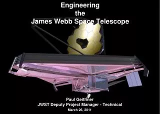
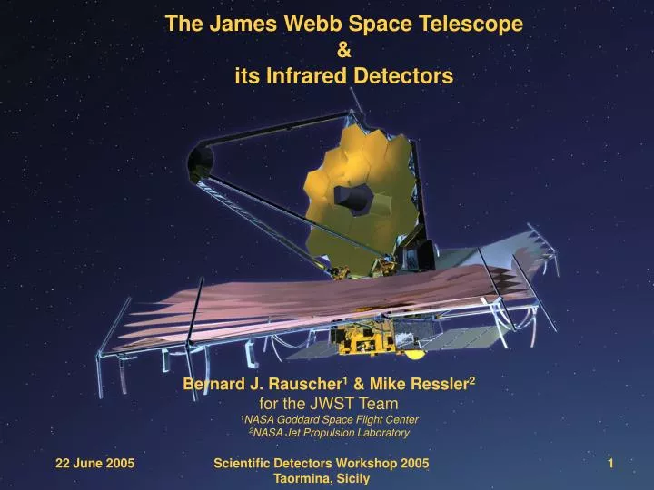
The James Webb Space Telescope & its Infrared Detectors. Bernard J. Rauscher 1 & Mike Ressler 2 for the JWST Team 1 NASA Goddard Space Flight Center 2 NASA Jet Propulsion Laboratory. 22 June 2005. Scientific Detectors Workshop 2005 Taormina, Sicily. 1. University of Arizona.

E N D
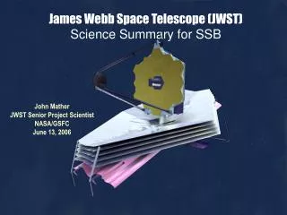
The James Webb Space Telescope&its Infrared Detectors Bernard J. Rauscher1 & Mike Ressler2for the JWST Team1NASA Goddard Space Flight Center2NASA Jet Propulsion Laboratory 22 June 2005 Scientific Detectors Workshop 2005Taormina, Sicily 1
University of Arizona Raytheon Vision Systems University of Rochester JWST’s Detector Partners The following individuals contributed material on JWST detectors to this presentationJames Garnett, Rockwell ScientificAlan Hoffman, Raytheon Vision SystemsMarkus Loose, Rockwell ScientificCraig McMurtry, U. Rochester In addition, we have drawn on other JWST-related documents as needed. These are cited when it is practical to do so. 22 June 2005 Scientific Detectors Workshop 2005Taormina, Sicily 2
Presentation Overview • JWST’s near and mid-IR wavelengths offer a very different perspective on the Universe compared to optical! • JWST Science • JWST Mission • Instruments, Detectors, and ASICs Spiral galaxy M81 seen in: (1) optical/Kitt Peak and , (2) 3.6 mm, (3) 8 mm, and 24 mm and (d) composite Spitzer images. Cosmic history from the Big Bang to today. JWST will elucidate the end of the dark ages and the beginnings of the galaxies that we see today. Scientific Detectors Workshop 2005Taormina, Sicily
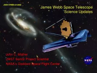
How and from what were galaxies assembled? What is the history of star birth, heavy element production, and the enrichment of the intergalactic material? How were giant black holes created and what is their role in the universe? Three instruments to do this: NIRCam (NASA/CSA), NIRSpec (ESA), MIRI (ESA/consortium/NASA), plus FGS-TF (CSA) Top JWST Goal - Find the First Light after the Big Bang as seen by COBE ? Galaxy assembly ? Galaxies, stars, planets, life
JWST Science • End of the dark ages: first light and reionization • The assembly of galaxies The Eagle Nebula as seen by HST The Eagle Nebula as seen in the near-infrared • Birth of stars and protoplanetary systems • Planetary systems and the origins of life Galaxies in the UDF Scientific Detectors Workshop 2005Taormina, Sicily
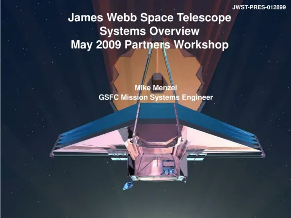
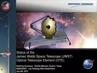
James Webb Space Telescope (JWST) • Mission Objective • Study the origin and evolution of galaxies, stars and planetary systems • Optimized for infrared observations (0.6 –28 m) • Organization • Mission Lead: Goddard Space Flight Center • International collaboration with ESA & CSA • Prime Contractor: Northrop Grumman Space Technology • Instruments: • Near Infrared Camera (NIRCam) – Univ. of Arizona • Near Infrared Spectrograph (NIRSpec) – ESA • Mid-Infrared Instrument (MIRI) – JPL/ESA & European Consortium • Fine Guidance Sensor (FGS) – CSA • Description • Deployable telescope w/ 6.5m diameter segmented adjustable primary mirror • Cryogenic temperature telescope and instruments for infrared performance • Launch in 2012 to Sun-Earth L2 • 5-year science mission (10-year goal) www.JWST.nasa.gov today ... Concept Development Design, Fabrication, Assembly and Test science operations mission formulation confirmation for launch authorized mission implementation
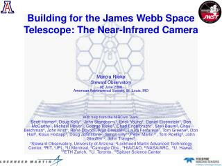
Instrument Overview Fine Guidance Sensor (FGS) • Ensures guide star availability with >95% probability at any point in the sky • Includes Narrowband Imaging Tunable Filter Module • CSA/EMS provided • 2 (2048x2048) 68mas pixels • John Hutchings, lead Mid-Infra-Red Instrument (MIRI) • Distinguishes first light objects; studies galaxy evolution; explores protostars & their environs • Imaging 1 (1024x1024) 110mas pixels • Spectroscopy (R~3000) 2 (1024x1024) 200-470mas pixels • 5 to 27 microns; Cooled to 7K by cryocooler • ESA/JPL, George Rieke, Gillian Wright leads Near Infra-Red Camera (NIRCam) • Detects first light galaxies and observes galaxy assembly sequence • 0.6 to 5 microns, 2 (4096x4096) 31mas pixels & 2 (2048x2048) 62mas pixels • Supports Wavefront Sensing & Control • Univ. of AZ - LMATC instrument; Marcia Rieke, PI Near Infra-Red Spectrograph (NIRSpec) • Measures redshift, metallicity, star formation rate in first light galaxies • 0.6 to 5 microns • Simultaneous spectra of >100 objects • 2 (2048x2048) 100mas pixels • Resolving powers of ~100, ~1000, ~3000 • ESA/Astrium provided, with NASA Detectors & Microshutter Former locationof dewar
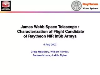
Infrared Detectors for JWST • Rockwell Scientific selected for NIRCam, NIRSpec and possibly FGS • Total of 19 Hawaii-2RG sensor chip assemblies (SCAs) for flight and flight spare • Raytheon Vision Systems selected for MIRI • Total of 6 SB-305 SCAs for flight and flight spare
HgCdTe NICMOS 256x256 WFC3 1024x1024 JWST Proto-type 4Kx4K Near-Infrared Detector Technology Development • NICMOS and IRAC arrays demonstrated the basic detector architecture but with lower performance and smaller formats. • TRL 4 achieved Feb 2002 with JWST performance levels achieved • TRL 5 achieved Feb 2003 with JWST size 2Kx2K devices, mosaicing • Astronomical Image with prototype, Sept. 2003 Scientific Detectors Workshop 2005Taormina, Sicily
Image with JWST Prototype Detector NGC 891 test image with Rockwell HgCdTe 4Kx4K array, Sept. 2003 The first astronomical image to be obtained on JWST flight prototype near-infrared detectors. This three color image of the galaxy NGC891 was obtained using a 4096 x 4096 HgCdTe array produced by Rockwell Scientific Corporation under contract to JWST and the University of Hawaii KSPEC instrument on the UH 88 inch telescope. Scientific Detectors Workshop 2005Taormina, Sicily
Near-Infrared Detector Readout & Control • SCA Control by Rockwell SIDECAR ASIC • One ASIC per SCA • Demonstrated performance met challenging JWST requirements in Feb., 2005 • JWST will fly a total of 16 near-infrared SCAs and 16 SIDECAR ASICs Scientific Detectors Workshop 2005Taormina, Sicily
Near-Infrared SCA Performance with SIDECAR ASIC • Quiescent lab conditions • Raw data & noise measurements as reported by Rockwell • Independent analysis of the same data at NASA/GSFC confirms Rockwell findings for CDS and MULTIACCUM*. Did not look at Fowler sampling • Flight representative • 2.5 mm cutoff SCA • SCA to ASIC electrical interfaces • ASIC Total Noiseper 1000 s The above figure was presented by Rockwell Scientific as part of an ASIC review package. Test data and analysis are by Rockwell staff. Baseline NIRSpec mode shown in Red. Uses 88 non-destructive samples up t~1000 s ramp. *For the data that were provided, we found that we needed one additional calibration step compared to Rockwell. The additional step was similar to correcting for a small pedestal drift. It was needed because the reference pixels did not perfectly track the regular pixels.
SIDECAR ASIC Exceeds JWST Noise Requirements • SIDECAR ASIC has demonstrated excellent noise performance that exceeds the requirements for all three near-infrared instruments (37 K SWIR H2RG + ASIC) 1100 kHz pixel rate 2 MULTIACCUM-22x4 calculated using 4 out of 6 measured ramps due to larger frame-to-frame pedestal in remaining 2 ramps. 3Analysis of test data independently confirmed by NASA/GSFC Test results & analysis reported on this slide provided by Rockwell Scientific. Except where indicated, they have not yet been independently confirmed by NASA/GSFC.
Near-Infrared Dark Current Tests Have Achieved the Required Levels Engineering Unit JWST-009, substrate removed SWIR array, dark current histogram and map Test results & analysis reported on this slide provided by Rockwell Scientific. Except where indicated, they have not yet been independently confirmed by NASA/GSFC. Test results reported on this slide provided by Rockwell Scientific
Visible QE Exceeds 80% at 800 nm Engineering Unit JWST-009, substrate removed SWIR array, QE histogram and map at 800nm - illumination non-uniformity not removed Test results & analysis reported on this slide provided by Rockwell Scientific. Except where indicated, they have not yet been independently confirmed by NASA/GSFC. Test results reported on this slide provided by Rockwell Scientific
Longer Wavlength QE Exceeds 80% As Expected Engineering Unit JWST-009, substrate removed SWIR array, QE histogram and map at 1230nm - illumination non-uniformity not removed Test results & analysis reported on this slide provided by Rockwell Scientific. Except where indicated, they have not yet been independently confirmed by NASA/GSFC. Test results reported on this slide provided by Rockwell Scientific
Mid-Infrared Technology Development • Concept studies for a JWST mid-IR instrument begun in 1997 • Tentative detector requirements laid out in these studies • Craig McCreight led the Detector Working Group in 1999 • Looked at all technologies applicable to JWST • Concluded Si:As IBCs were most mature for mid-IR • Produced “Document 641” – JWST detector roadmap • Contract with Raytheon in ~ 2000 to develop Si:As technology for JWST established by Craig • JPL selected as U.S. MIRI lead in 2001 • MIRI detector competition announced inearly 2003 • Raytheon competitively selected in May2003 • PDRs begun in August 2003 thatfinalized design Hybrid shown in a non-flight test mount Scientific Detectors Workshop 2005Taormina, Sicily
MIRI Focal Plane Primary Requirements Parameter Format Detector Material Noise (Fowler-8 sampling) Dark Current QE: 5 – 6 um 6 – 12 um 12 – 26 um 26 – 28.2 um Requirement 1024 x 1024 Si:As IBC < 19 e- @ 7.1 K < 0.03 e-/sec @ 7.1 K > 40% > 60% > 70% > 5% (goal) Measured 1024 x 1024 Si:As IBC 10 e- @ 7.1 K <0.1 e-/sec @ 7.1 K (test limit) > 50%* > 60%* > 70%* (12 – 24 um) > 30%* (24 – 26 um) > 5%* * QE estimated from AR coat reflectance measurements and QE measurements on non-AR coated detectors Test results & analysis reported on this slide provided by Raytheon & their partners. Except where indicated, they have not yet been independently confirmed by NASA/JPL. See Hoffman, A. et al. poster this conference Scientific Detectors Workshop 2005Taormina, Sicily
Raytheon Detector Assembly Design Cover/Baffle 51 Pin Electrical Connector SCA Attachment Feet Motherboard Cable Pedestal Cold Strap Interface Thanks to RVS staff: Roger Holcombe, Rich Mullins, Barbara Ceriale, Margaret Olowski
Focal Plane Module Design 20mm Thick Al 6061-T6 Back Cover Plate M5 Through Holes Detector Assembly Temp Sensor Connector SCA Connector Titanium Thermal Strap Support With M6 Bolt OBA Interface Plane With Locating Pin and Slot Al 6061-T6 Cable Closeout Plate Bonded Fiberglass Thermal Port
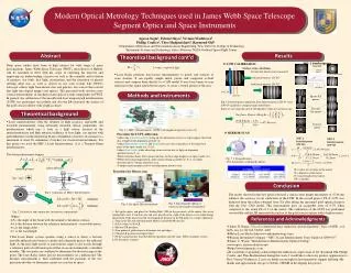
Relative Spectral Response Comparisons Test results & analysis reported on this slide provided by Raytheon & their partners. Except where indicated, they have not yet been independently confirmed by NASA/JPL. See Hoffman, A. et al. poster this conference Scientific Detectors Workshop 2005Taormina, Sicily
ROIC Read Noise at 7.1 K "Read noise versus Fowler Sampling at 7.1K for ROIC 1-25-C2. The integration time was 25 sec for all Fowler sampled images. Please note that one box was in a region that gave consistently higher noise which is due to excess row-banding in the first 80 rows. There is an occasional second point with higher noise due to cosmic ray hits (which were not filtered out). Therefore, we feel it is valid to ignore the 1-2 points outside the major groupings at each sampling." 10 e- (Fowler-8) 2.5x lower noise than SIRTF/IRAC Test results & analysis reported on this slide provided by Raytheon & their partners. Except where indicated, they have not yet been independently confirmed by NASA/JPL. See Hoffman, A. et al. poster this conference