Download
1 / 13
130 likes | 251 Views
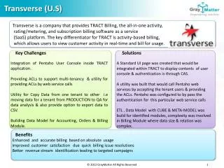
Transverse Feed Assembly Analysis. Transverse Feed Assembly. Motion in the X and Y direction was initially planned to occur exclusively in the base plate of the mill Mount the vacuum table on two linear slides perpendicular to each other

E N D
Transverse Feed Assembly • Motion in the X and Y direction was initially planned to occur exclusively in the base plate of the mill • Mount the vacuum table on two linear slides perpendicular to each other • Wire Management will be more manageable than with a gantry system • With less movement of the spindle head, likely to be more accurate
Analysis of XY Base Plate motion • Initial Vacuum Table Weight Estimate- 40 lbs max • Contacted Isel USA, a linear slide company to get more information about their rail and table systems • Technical suggestions for our project from a Engineer Support Representative • Helped with NEMA Motor selection • Gave a cost estimate for their system
Advice from Isel USA Rep • For the most part, when doing the milling, you can’t go very fast because the tool diameters are very small and the cutting forces are relatively small so going to the NEMA 34 motors tends to be a waste of money for the motors and amplifiers. • If you want to do milling type applications, then the Z will have to be motorized as well otherwise you are pretty much constrained to single level milling.
Advice from Isel USA Rep • Each slide with a stepper motor that has about 6” of travel is $1124.00 each. • The next step up is a slide with about 10” of travel and these are $1230.77 each. • I would suggest a format such as:
Advice from Isel USA Rep • With a structure made of support brackets and extrusions to hold the Z axis above this • We would build a bridge above this using a couple of pieces of extrusion. • The structure and brackets would be about $1850.00 • The 3 axis electronics would be $1332.78. This includes PAL as well as the ability to run in DNC mode (long programs that don’t fit into memory and are drip fed) and CNC mode (short programs that can be downloaded to memory) • Motor cables range in price from about $130 each to about $150 each depending on the length (3m to 5m). • You still need the isolation software to go with this. Galaad offers a free software package to do isolation when you buy their basic control package. I will find out about this if you are interested.
Transverse Feed Cost Estimates • Isel USA systems cost upwards of $3000- way over our budget • Other sources- these types of systems are more expensive than expected- $350 for just the slides, around $700 for entire structure.
Mobile Bed vs. Mobile Gantry Mobile Bed Design +Typically found on smaller CNCs (PCB, engraving, etc.) +Sturdy, will not flex under load +Better wire management - Requires a larger footprint - Must Consider moving the weight of the table - Hard to support router/spindle
Mobile Bed vs. Mobile Gantry Mobile Gantry Design +Can be designed to be as sturdy as a fixed gantry +Most popular for DIY CNC routers +Can be arbitrarily large- Must consider weight and size of the gantry - Must account for deflection and vibration
Gantry System Cost Estimates • DIY CNC Gantry Kits for as low as $350 • This handles motion in the X and Y while also including the structural support for Z motion and Spindle.
Stepper Motor Calculations Equations from Shigley’s Mechanical Engineering Design (8-1) and (8-2)
Zen Toolworks CNC DIY Kit • Gantry supports are manufactured from PVC • Modulus of Elasticity 370 – 409 ksi • Easily replaced with Aluminum plate • Modulus of Elasticity 10,000 ksi • Refine gantry height
Final Selection • Mobile Gantry Design • NEMA 17 Stepper Motors