Download
1 / 49
490 likes | 592 Views
SuperNova Acceleration Probe Research and Development Efforts. Chris Bebek UC Berkeley Lawrence Berkeley National Laboratory. Instrument R&D areas. In the past year we have conducted a technical and scientific trade study covering a range of options for the SNAP instrumentation suite.

E N D
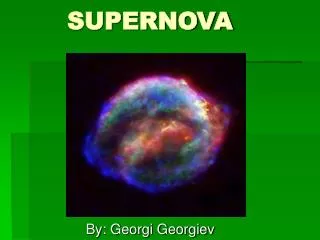
SuperNova Acceleration ProbeResearch and Development Efforts Chris Bebek UC Berkeley Lawrence Berkeley National Laboratory
Instrument R&D areas In the past year we have conducted a technical and scientific trade study covering a range of options for the SNAP instrumentation suite. We have arrived at a coherent instrument working concept and observation strategy constrained by reliability, satellite, thermal, orbit and telemetry issues described Mike Lampton and SNe characteristics that optimizes the science reach of SNAP. We have identified four risk areas and have an R&D program to address these: • CCDs • MTF/PSF • Cold irradiation • Fabrication • HgCdTe • QE • Readnoise • Fabrication • CCD readout • HgCdTe readout Chris Bebek
Measurement Program ~50 Type Ia SNe per 0.03 in z from z=0.3 to 1.7 (2500 total). Follow up spectroscopy near peak luminosity. Template building (spectra vs époque for subset of z<0.7 SNe). Photometry U, B, V, (R)-band light curves. B-band to 1% at peak. B–V color evolution. Malmquist bias. Rise time. Peak to tail ratio. Spectroscopy UV metalicity features – strength and location. S and Si features SII 5350Å line, Dw = 200Å SII “W” shape, Dw = 75Å SiII 6150Å line, Dw= 200Å Ejecta velocity, Dl >15Å Calibration Instrument Use two plate scales to cover the wavelength range to obtain time efficient photometry and a large FOV. Observation cadence commensurate with SNe evolution. Allocation of time for photometry and follow up spectroscopy. Imager Wavelength coverage from 350 nm to 1700 nm. 9 filters. Cadence of repetitive exposures matched to SNe evolution rate. Exposure lengths generate required S/N versus magnitude. Spectrograph Wavelength coverage from 350 nm to 1700 nm. S/N = 20 Resolution ~ 140 (l/dl) How Science-Driven Requirements map onto Instrument Concept Chris Bebek
Photometry illustration 1+z spaced B-band filters Chris Bebek
Spectroscopy illustration Metalicity SII “W” SiII Chris Bebek
Instrument working concept Guiders Cold plate Radiator Cables Thermal links Shield Spectrograph CCDs/ HgCdTe Shutter Filters FE Electronics Data/Monitoring/ Command Chris Bebek
Focal plane concept • Coalesce all sensors at one focal plane. • Imager sensors on the front. • 36 HgCdTe 2kx2k 18 mm • 36 CCD 3.5kx3.5k 10.5 mm • Filters • 1 of 3 per HgCdTe • 4 of 6 per CCD • Spectrograph on the back with access ports through the focal plane. • Common 140K operatingtemperature. • Dedicated CCDs forguiding from the focal plane. • Exposure times of 200 s with four/eight exposures in CCDs/HgCdTe. • 20 s readout slow enough for CCD noise and 4 post exposure and 4 pre exposure reads of HgCdTe. rin=6.0 mrad; rout=13.0 mrad rin=129.120 mm; rout=283.564 mm Chris Bebek
Integral Field Unit Spectrograph Design SNAP concept: Camera Detector Prism Collimator Slit Plane Small IFU, 2-arm spectrograph based on image slicer work performed for NGST. Image slicer Chris Bebek
Example scan Chris Bebek
Establishing detector requirements • Some sensor requirements are determined by SNe characteristics, eg, wavelength coverage. • Some characteristics are innate to the sensors, eg, QE(l). • Other requirements (eg, read noise, dark current) have been bounded by studying the desired S/N as a function of SNe epoch, exposure time, and number of exposures. • Example study of achieved S/N with four 200 s exposures and: • CCD • RN = 4 e- • DC = 0.02 e-/s/pix • Npix = 4 • HgCdTe • RN = 4 e- • DC = 0.02 e-/s/pix • Npix = 4 Requirement S/N>30 Dmag S/N>30 S/N>20 S/N>15 S/N>10 S/N>3 Chris Bebek
Derived Requirements for the Imager Note: Requirements for spectrograph use are similar. Chris Bebek
LBNL CCD technology Back-illuminated thick CCD on a high-resistivity n-type substrate, operated fully depleted. Advantages: 1) Conventional CMOS processes without super thinning. 2) Full quantum efficiency to >1 mm => no fringing. 3) Good blue response with suitably designed rear contact. 4) No field-free regions for charge diffusion, good PSF. Drawbacks: 1) Enhanced sensitivity to radiation (x-rays, cosmic rays, radioactive decay). 2) More volume for dark current generation. 3) Dislocation generation. The technology has been transferred to DALSA and “rad hard, p-channel, high resistivity capability” is now listed on their web site. Chris Bebek
LBNL CCD evolution 100 mm LBNL-fabbed 2kx2k 100 mm DALSA 2kx2k 100 mm LBNL-fabbed 2kx4k 150 mm DALSA PIN diodes 150 mm DALSA 2kx2k & 3kx3k Chris Bebek
Near-IR vs Visible imaging WIYN 3.5m with LBNL 2048 x 2048 CCD (Dumbbell Nebula, NGC 6853) Blue: H- at 656 nm Green: SIII at 955 nm Red: 1.02 mm Chris Bebek
LBNL 2k x 2k results Image: 200 x 200 15 m LBNL CCD in Lick Nickel 1m. Spectrum: 800 x 1980 15 m LBNL CCD in NOAO KPNO spectrograph. Instrument at NOAO KPNO 2nd semester 2001 (http://www.noao.edu) Chris Bebek
CCD issues • Pixel size • Well depth • Linearity • Dark current • Persistence • Read noise • MOSFET operation • Charge transfer efficiency • Quantum efficiency • Diffusion • Intrapixel response • Radiation • Proton damage • 60Co • Damage when cold • Fabrication Chris Bebek
Pixel size Well depth Linearity Dark current Persistence Read noise MOSFET operation Charge transfer efficiency Quantum efficiency Diffusion Intrapixel response Radiation Proton damage 60Co Damage when cold Fabrication 10.5 m work. 130 ke for 10.5 m pixel. Better than 1%. 2-5 e/hr/pixel. Erase mechanism is effective. 2.0-2.5 e. Documented at operating temperature. CTI ~ 10-6 pre-irradiation. Extended red performance realized. On-going study. On-going study. More robust than existing space devices when damaged warm. No surprises for T=300K dosing.(won’t discuss today). An activity during the next 3 months. Partially commercialized. Performance R&D areas Chris Bebek
LBNL 2k x 2k Quantum Efficiency Chris Bebek
MTF/PSF issues • We are ~2x undersampled. • Uniformity and simplicity of PSF determines the amount of image dithering that will be required. • Diffusion – the fundamental ~gaussian spread of charge as it drifts from the photon conversion site to a pixel. • For conventional CCDs, the rms spread is the depletion depth, ~10 mm. • For LBNL CCDs, the rms spread is determined by thickness and the sq.rt. of the depletion voltage. • We require 4 mm. E.g., t = 200 mm, Vsub = 100V, s = 3.2 mm. • We are working on routine thinning to 200 mm and beginning the study of device robustness versus Vsub (we have routinely operated in the lab at 60V with excursion to 140V). • Intra-pixel response – after diffusion drift, does the charge hit the “correct” pixel. • 2D modeling of conventional CCDs and LBNL CCDs with its substrate voltage shows good termination of the field lines on pixels. • Measurements – we are commissioning a pinhole projector to measure diffusion as a function of voltage and thickness and to map intrapixel response. Chris Bebek
Diffusion/intrapixel response measurements We are commissioning a pinhole projector, ~4 m FWZ, to scan the backside of the CCD looking for charge collection variations in vicinity of pixel edges. We have scanned the front side so far and see the polysilicon gate structure. Backside scans any minute now. Front-side scans Chris Bebek
Radiation environment • Integrated for three years, SNAP will be exposed to: • A few krad (Si) TID. • A few 107 MeV/g NIEL. • Note: • 1x10⁹ protons/cm2 @ 12 MeV is 1.5x10⁷ MeV/g NIEL. • 1x10⁹ protons/cm2 @ 12 MeV is 500 rad. Chris Bebek
Proton irradiation studies 12 MeV protons onto CCDs • We used 12 MeV protons at the LBNL 88” Cyclotron • Two set of four device were irradiated at room temperature. • Doses were 5x10⁹, 1x10¹⁰, 5x10¹⁰ and 1x10¹¹ p/cm2. • We characterized the devices by measuring their CTE and dark current as a function of temperature. Chris Bebek
Dark Current Degradation Dark current is measured with one thousand or more second exposures. The gaussian charge distribution in the active region of the CCD is compared with the gaussian change distribution in the overscan region. SNAP Fit gives expected Si bandgap, so no new dark current sources are developing. The plateau at right is not identified yet, but could be surface leakage currents. Chris Bebek
Charge transfer efficiency CTE is measured using the 55Fe X-ray method at 128 K. The readout speed is 30 kHz, the X-ray density is 0.015/pixel. Degradation is about 110-13 g/MeV. Comparison to conventional CCDs after converting dose to NIEL (MeV/g). SNAP Caveat. We irradiated parts at 300K and unpowered. While we have compared apples with apples, our study will be complete only after performing damage at operating temperature and powered. Will try to complete this this summer. [1]L.Cawley, C.Hanley, “WFC3 Detector Characterization Report #1: CCD44 Radiation Test Results,” Space Telescope Science Institute Instrument Science Report WFC3 2000-05, Oct.2000 [2] T. Hardy, R. Murowinski, M.J. Deen, “Charge transfer efficiency in proton damaged CCDs,” IEEE Trans. Nucl. Sci., 45(2), pp. 154-163, April 1998 SNAP Chris Bebek
CTE vs Temperature at 1x10¹¹ p/cm2 Both serial and parallel CTE exhibit significant temperature dependence due to interactions with radiation induced trapping centers. Chris Bebek
Hole Traps Found in n-Type Si Trap parameters measured using DLTS V V + V VV Proton Irradiation CiOi Sii Ci CiCs Chris Bebek
Fitted trap density versus dose Chris Bebek
100 mm wafer fabrication • LBNL manufactured • We have fabricated 10.5, 12, and 15 mm devices in a variety of formats up to 2kx4k. • These have ranged from 190 to 300 mm thick. • Some of these devices are deployed in ground telescope. • Recently, much effort has gone into developing careful handling procedures and equipment modifications to protect the backside of the wafer during manufacture. • DALSA manufactured • Our process technology transfer first done here. • 15 mm devices up to 2kx2k have been successfully built. • Devices as thin as 200 mm have been finished. Chris Bebek
150 mm wafer fabrication • DALSA work • They have converted exclusively to 150 mm wafers. These wafers are must be thinned from ~675 mm to 200 mm for our use. • Unthinned photodiode wafers have been fabricated with good results. • A few thinned wafers have been fabricated. We found similar backside “damages” areas that we have already eliminated at LBNL. • Unthinned CCD wafers have been fabricated that were of high quality in front illuminated studies. • We have received one thinned (300 mm) CCD wafer that is now under backside illumination tests. • LBNL work • We are gradually transferring our backside handling knowledge to DALSA but expect this to take some time to fully implement. We view this as the second phase of our commercialization effort. • In the meantime, we have acquired the one piece of 150 mm processing equipment that will allow us to perform the last steps of wafer processing – contacts, metalization, AR coating. • DALSA will provide 675 mm thick CCDs where the front side is complete, device is thinned, and backside thin poly is deposited, This includes all the conventional CMOS process steps. We will continue to work with them on thinning issues with fully automated processing equipment. Chris Bebek
Example of backside “damage/particles” before remedies MTI resist dispense chuck Aligner handler cups PE641 aligner chuck (waffle pattern) Chris Bebek
LBNL efforts on backside particles/damage Backside processing issues and remedies to be transferred to DALSA. • Back side scratches through ISDP layer fatal for fully-depleted operation • Avoid where possible handlers made from materials that can scratch silicon • Improved wafer carriers for MRC sputtering system • Manual override of wafer alignment arm on MTI resist dispense arm • Use of sacrificial SiO2 layer on wafer backside • Not scratch immune but allows for undercut of particles during strip • Particle removal via wafer scrubbing (most effective technique to date) • Use of wear resistant materials on vacuum chucks and wafer handlers where possible (DuPont VESPEL effective but does shed particles) • Avoid use of silicone parts (cannot remove with scrubbing) • First wafers through equipment (coater, aligner) tend to have significantly higher particle counts • Photoresist aerosol particles – too large to be removed with ashing, require addition of solvent to scrubbing soap solution • LBNL experience: particles can be removed with mechanical action (scrubbing). Main concern is damage through thin backside poly layer. Chris Bebek
Rockwell HgCdTe • Rockwell HgCdTe devices are our only option at the moment. • WFC3 MBE material with 1.7 mm cutoff is a perfect match to SNAP. • NGST 2k x 2k format being developed is also a good match. • Status (as of March) • The dark current is OK. • There is a QE “problem” in the 900 nm to 1100 nm region. • There is a large read noise, ~30 e, not the design goal of 10 e. • Long-term drifts and settling times are seen at some test sites. • Rockwell claims they understand the MBE knobs that control QE. • They are have grown new material (1k x 1k). • It is presently being bumped and packaged. • The large read noise is bad for SNAP • We want to rt-N this down to 5 e, ie, four CDS reads take 10 e to 5 e. • More reads have a big impact on observation time budget. • Rt-N has only got to 17 e so far (there may be new info on this). Chris Bebek
MTF/PSF issues • We have studied the impact of a “gutter” around each pixel as existed in the PACE devices (this is NOT present in the MBE devices). The impact of that dead region relative to a device without it was to double the number of exposures required to obtain equivalent photometry. • Intrapixel response for the MBE HgCdTe has not been measured yet. • We will acquire a device to measure this ourselves. We have ordered a mux to begin setting up a measurement system with pin hole projector. • Intrapixel response may be just fine as it is or it may not be. If not, Rockwell has posited: • Design changes of the implants near the PN junctions. This is essentially tuning up the electric fields to better capture the charge. • Etching microlenses into the CdZnTe substrate to focus photons on the pixel sweet spot. Chris Bebek
CCD support electronics • Goals: • Photons-to-bits focal plane • Eliminate large cable plant to reduce system noise problems. • Reduce power dramatically relative to conventional implementation. • ASIC Challenges: • Large voltages • ~10 V clock swings • ~20 V MOSFET biases • ~32 V span within CCD, excluding depletion voltage • Large dynamic range from 2 e- readnoise and 130 ke- well depth. • Radiation tolerance (borrowed from GLAST for now) • Total ionizing radiation dose: performance maintained up to 10 Krad (Si). • Single-Effect Latch-up (SEL): immune to a minimum LET of 40-80 MeV-cm2/mg. • Singe-Effect Upset (SEU): performance maintained for a LET of at least 8 MeV-cm2/mg. • Operation at 140K to reduce cable plant and associated problems – requires low power Chris Bebek
Readout Electronics Concept • CDS – Correlated Double Samples is used for readout of the CCDs to achieve the required readout noise. • ADC – 16-bit dr, 12-bit res 100 kHz equivalent conversion rate per CCD. • Sequencer – Clock pattern generator supporting • modes of operation: erase, expose, readout, idle. • Clock drivers – Programmable amplitudes. Supports 4-corner or 2-corner readout. • Bias and power generation – Provide switched, • programmable large voltages for CCD and local power. • Temperature monitoring – Local and remote. • DAQand instrument control interface – Path to data buffer memory, master timing, and configuration and control. Chris Bebek
ASIC roadmap We are working with LBNL ASIC designers to address CCD clock generation, bias voltage generation, and analog signal processing in one or more ICs. Correlated double sampler • Starting here since it has the most challenging analog issues. • We have performed a survey of sub-micron CMOS processes. • We have evaluated system noise for different technologies and signal processing schemes. • We have measured pre and post irradiated test structures as a function of T. • We will design a CDS circuit for fabrication over the next 4 months. ADC • This could be part of CDS circuit, so we are thinking of implementations in parallel with CDS development. • We are exploring a 12-bit pipeline ADC with three ranges. Clock drivers • Pattern generator is an “easy” digital design. • Amplitude control of large voltages will be challenging. • Study of rad tolerance of 40 V sub-micron CMOS. Chris Bebek
CCD MOSFET noise Measured noise spectral density at low temperature for an LBNL CCD MOSFET. Chris Bebek
Noise comparison (PMOS) PMOS noise spectral density for several vendors derived from their technology models. Model results have been validated by test data from others. Chris Bebek
Differential averager CCD noise + first stage noise • Pmos Agilent 0.5mmIC = 1, Id = 100mA • Nmos TSMC 0.25mm • IC=0.1, Id = 100mA C (100pF) Dt R t Out X1 CCDnoisesource (Noiseless) t -X1 Integrator voltage gain: 2 Integration time t Conversion gain: 3.5mV/e Input referred noise (e) Dt = 0 4ms (R=20KW) (1) 2.8 / (2) 2.9 t t 8ms (R=40KW) (1) 2.1 / (2) 2.2 10ms (R=50KW) (1) 1.92 / (2) 2 The 1/f noise of the input stage is reduced by the CDS The thermal noise from the input stage is negligible compared to the CCD Chris Bebek
TSMC 0.25 mm cold CMOS Threshold voltage NMOS Threshold voltage PMOS ~1mV/K ~1mV/K Mobility ratio NMOS After rad means >10 Mrad. Mobility ratio PMOS UTE = -1.3 UTE = -0.7 Chris Bebek
Sub-micron CMOS comments • Sub-micron CMOS appears to perform well down to 100K. • Vendor BSIM3 SPICE model predicts performance down to 150K region. • Technology is extremely rad hard. • LBNL has the “rad hard by design” methodology to build robust systems. • As with CCDs, rad testing at cold temperature needs to be explored. • Sub-micron 40V processes need careful radiation study because of the thick oxide used. [Our default plan is to use external JFETs as voltage boosters for clock and bias drivers.] Chris Bebek
HgCdTe readout • Inputs to readout architecture • Advertised single CDS noise is to be 10 e; we require 5 e. • Therefore, we need four pre and four post exposure reads. • To accomplish 8 reads in 20 s at 100 kpixel/s rate requires 16 taps per 2kx2k device. H2-RG has 32 taps. • Desirable to do pre and post read averaging in hardware. • There is a Rockwell initiative for the NGST mux readout for an ASIC operated cold adjacent to the sensor • Five 16-bit ADCs (intended for 4 tap readout) • Microprocessor based timing sequencer • Data processing • Can implement co-adding and averaging at the pixel and line level. • Power including mux is ~2 mW per read port. • R&D issues • Trade study of using existing H2-RG mux or developing one with 16 taps. • Ability to cascade multiple Rockwell ASICs to achieve more ADCs per H2-RG. • Development of our own ASIC. Chris Bebek
R&D Summary • CCD • Study operation at high depletion voltage to minimize diffusion. • Measure intrapixel response. • Radiation damage at 140K. • Refine fabrication process. • Establish “production yield.” • HgCdTe • Read noise needs to be reduced. • Track QE developments. • Establish “production yield.” • CCD electronics • Radiation measurements at 140K. • Fabricate demonstration CDS/ADC in 0.25 mm CMOS during the next year. • Radiation study of 40V sub-micron CMOS. • HgCdTe electronics • Refine commercial solution, if it exists, to SNAP needs. • Or, develop our own readout. Chris Bebek