Download

1 / 28
290 likes | 467 Views
Device-level Radiation Effects Modeling. Hugh Barnaby, Jie Chen, Ivan Sanchez Department of Electrical Engineering Ira A. Fulton School of Engineering Arizona State University. Topics. Target of Research Radiation Effect Modeling: A TCAD-based approach

E N D
Device-level Radiation Effects Modeling Hugh Barnaby, Jie Chen, Ivan Sanchez Department of Electrical Engineering Ira A. Fulton School of Engineering Arizona State University
Topics • Target of Research • Radiation Effect Modeling: A TCAD-based approach • Example: Drain-source leakage in deep-submicron bulk CMOS
Goals • Model the effects of TID and DD defectson advanced device technologies • Identify the continuing and emerging radiation threats to these technologies • Model the defects: implement physical models, dynamics of buildup • Radiation effects testing (Co60, neutrons, low temperature testing)
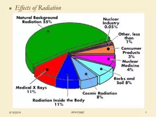
Radiation Concerns • Total ionizing dose • Displacement damage • Single event damage and micro-dose
Technologies and Techniques • Ultra Thin Oxides • Shallow Trench Isolation • Buried Oxides • Implants • Heterojunctions • Gate technologies
Device Categories • Ultra Small Bulk CMOS • Silicon on Insulator (dual gate operation) • Strained Silicon CMOS • SiGe HBTs ASU has a strong relationship with FreeScale semiconductor.
Effects • Oxide Damage and Reliability • Defect buildup • Leakage • Breakdown • Annealing and other temperature dependent processes • Semiconductor Effects • Electrostatics • Carrier recombination and removal • Mobility effects • Annealing and other temperature dependent processes
Testing • Co60 g-sources • ASU (100 rd/s, 1 rd/s, ~10mrd/s) • UA (100 rd/s, 10 md/s) • Neutron Sources (UA – Triga and Rabbit Reactors) • Low temperature Co60 irradiations (down to 70k)
TCAD Modeling and Simulation TCAD Flow Process and Layout Description Design Bias Conditions To EDA Process Sim. Device Sim. Circuit Sim. OPTIMIZESTRUCTURE GEOMETRY OPTIMIZE ELECTRICAL PERFORMANCE PROCESS DEVICE CIRCUIT Ileak NET DOPING POTENTIAL Vd 2D potential contours in parasitic nMOSFET Leakage current vs. drain voltage SRAM Schematic including parasitic nMOSFET element 2D cross section of LOCOS parasitic nMOSFET
Radiation Effects Modeling Strain effects, energy to defect conv., doping profiles heating, defect formation, tunneling. Displace.Damage carrier transport in dielectric, defect formation and approximations TotalDose Defect precursors Bias Conditions Process and Layout Description Process Device OPTIMIZE GEOMETRYAND PRECURSORS
Example: D-S Leakage ++ + + Due to aggressive scaling into the deep sub-micron, the threat of significant threshold voltage shifts caused by charge buildup in the gate oxide has been reduced. Instead threats have shifted elsewhere, such as drain-to-source leakage caused by charge buildup in the isolation oxide (shallow trench – STI) STI shallow trench isolation oxide N+ Source + + + + + + Polysilicon gate N+ drain Leakage Leakage
TID effects on off-state leakage • Increase in off-state leakage (ID @ Vgs = 0V) increases to 100nA after 400 krad of exposure. • Problem in SRAM arrays (power, overheating, and failure) After Lacoe NSREC SC 2003
TI-MSC1211 A/D Converter • 24-bit Delta-Sigma ADC • Internal reference generator • Intel 8051 microcontroller • Timers • Universal asynchronous receiver and transmitter • RAM, ROM, and flash memory Vsupply Isupply Temperature monitor, RTD (resistant temperature device),mounted on package measure specifications
Offset Calibration • Bit-error outputfor differential input • High frequency datarepresents noiseinduced offsets • Mean value determinedby device mismatch,temp variation, etc. Other specs include: full scale, and ENOB
Supply Current and Temperature Digital Supply Current vs. DOSE TID leads to increase inoperating temperatureof device. Package Temperature vs. DOSE Field oxide leakage path
Photoemission Analysis Increased power dissipationand die temperature causedby high static current densityin pre-charge devices of SRAM array. Vsupply Field oxide leakage path
Mechanism Increased current density reveals impact of radiation-induced leakagemechanism: the parasitic nMOSFET.
Parasitic nMOSFET L L L L W W W W STI STI parasitic nMOSFET PRE-RAD Due to its greater oxide thickness, the parasitic nMOSFET has a much higher VT and lower drive current compared to “as drawn” device. POST-RAD Due to its greater oxide thickness, oxide-chargebuildup in the parasitic nMOSFET is much greater,causing large shifts in VT drive current. “as drawn” nMOSFET VT “as drawn” nFET parasitic nFET 11 VT (10 ) VT (0) 12 13 VT (10 ) VT (10 ) Drive current Drive current Increasing TID
Parasitic nMOSFET Parameters “As Drawn” nFET “As Drawn” Parasitic tox Weff Vt ParasiticnFET Circuit modeling of leakagerequires accurate extractionof key parasitic parameters: threshold voltage, effectivewidth, and oxide thickness
2D Modeling Approach Standard 2-edge device 2D Cross-section along cutline gate + Cutline Not + + + STI Drain Source + + Si Not +++ + Gate + uniform oxidecharge (Not) Modeling on IBM 0.13um 8RF CMOS
2D Modeling Results Not = 5x1012 cm2 (uniform) Vgs = 0.2V + + Combination of Not, gate bias,and device properties creates electron inversion layer at theSTI edge + + + electroninversionlayer +
Definition of Threshold Voltage bulk potential(fB) Inversion potentialEf – Ei(0) = f Threshold voltage is thegate voltage at which theinversion potential (f) equalsthe bulk potential. Note: dependent on Not density and cutline depth.
Extracting Cox and tox VT of parasitic Slope Cox Cross overindicates TIDsusceptibility VT of “as drawn” Oxide Trapped Charge (1012 cm-2)
Effective width (Weff.) Parasitic nMOSFET width (Weff.) is dependent on oxide charge, gate bias,and other parameters. Not = 2x1012 cm2 Vgs = 0.2V Not = 5x1012 cm2 Vgs = 0.2V Not = 7x1012 cm2 Vgs = 0.2V W(2) W(5) W(7)
Effective width (Weff.) fs fB Weff Weffis calculated at afixed gate bias and chargedensity over a specifieddepth (Wo).
Volumetric TID Simulations … use TCAD rad effects modeling togenerate NOT as function of precursors,dose, dose rate, and electric field How to relate device response to dose, process, and bias conditions … Sheet Charge Trapped Charge vol. distribution
New CMOS Processing Issues Retrograde Channel dopingNon uniform doping profile used formodeling variation in channel doping. Strained silicon“Both [IBM and Intel] introduced strained silicon” in 90 nm. - Semiconductor Insights strained Si channel NS~ 1018 (ITRS 2002) NB > 1019 (Brews TED 8-00) d = 25 nm (ITRS 2002)
Impact of Retrograde • Without retrograde • wide channel • hi leakage Examine leakage channel inside box • With retrograde • thin channel • lo leakage Will D-S leakage be a problem for 90 nm?