Download

1 / 14
150 likes | 345 Views
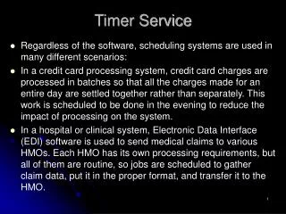
Timer 1. INTCON Register. The INTCON Register is a readable and writable register, which contains various enable and flag bits for the TMR0 register overflow, RB Port change and External RB0/INT pin interrupts. PIE1 Register.

E N D
INTCON Register • The INTCON Register is a readable and writable register, which contains various enable and flag bits for the TMR0 register overflow, RB Port change and External RB0/INT pin interrupts.
PIE1 Register • The PIE1 register contains the individual enable bits for the peripheral interrupts. • Bit PEIE (INTCON<6>) must be set to enable any peripheral interrupt.
TIMER1 MODULE • The Timer1 module is a 16-bit timer/counter consisting of two 8-bit registers (TMR1H and TMR1L), which are readable and writable. • The TMR1 Register pair (TMR1H:TMR1L) increments from 0000h to FFFFh and rolls over to 0000h. • The TMR1 Interrupt, if enabled, is generated on overflow, which is latched in interrupt flag bit TMR1IF (PIR1<0>). This interrupt can be enabled/disabled by setting/clearing TMR1 interrupt enable bit TMR1IE (PIE1<0>). • Timer1 can operate in one of two modes: • As a timer • As a counter
Timer 1 contd.. • The operating mode is determined by the clock select bit, TMR1CS (T1CON<1>). In Timer mode, Timer1 increments every instruction cycle. • In Counter mode, it increments on every rising edge of the external clock input. • Timer1 can be enabled/disabled by setting/clearing control bit TMR1ON (T1CON<0>). • When the Timer1 oscillator is enabled (T1OSCEN is set), the RC1/T1OSI/CCP2 and RC0/T1OSO/T1CKI pins become inputs. That is, the TRISC<1:0> value is ignored, and these pins read as ‘0’.
Timer1 Operation in Timer Mode • Timer mode is selected by clearing the TMR1CS (T1CON<1>) bit. In this mode, the input clock to the timer is FOSC/4. • The synchronize control bit T1SYNC(T1CON<2>) has no effect, since the internal clock is always in sync.
Timer1 Counter Operation • Timer1 may operate in either a Synchronous, or an Asynchronous mode, depending on the setting of the TMR1CS bit. • When Timer1 is being incremented via an external source, increments occur on a rising edge. • After Timer1 is enabled in Counter mode, the module must first have a falling edge before the counter begins to increment.
Timer1 in SynchronizedCounter Mode • Counter mode is selected by setting bit TMR1CS. In this mode, the timer increments on every rising edge of clock input on pin RC1/T1OSI/CCP2, when bit T1OSCEN is set, or on pin RC0/T1OSO/T1CKI, when bit T1OSCEN is cleared.
Resetting of Timer1 Register Pair(TMR1H, TMR1L) • TMR1H and TMR1L registers are not reset to 00h on a POR, or any other RESET, except by the CCP1 and CCP2 special event triggers.