Download
1 / 24
240 likes | 422 Views
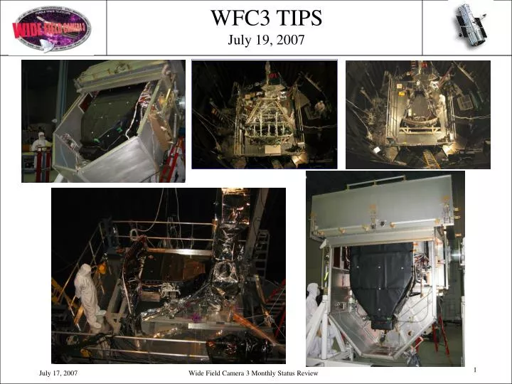
WFC3 TIPS July 19, 2007. Summary. WFC3 halfway through Thermal Vacuum Test #2 Team is performing excellently and test is on schedule Several thermal issues discovered which will require modifications Internal calibration lamps have multiple problems

E N D
Summary • WFC3 halfway through Thermal Vacuum Test #2 • Team is performing excellently and test is on schedule • Several thermal issues discovered which will require modifications • Internal calibration lamps have multiple problems • Great progress on closing out liens from 2004 TV test • Currently 39 days into the maximum 72 day T/V-2 test (SES chamber must be vacated and certified for the next HST test by 9/1/2007) • Flight detector development • Two outstanding IR flight detectors in packaging flow at Ball with installation of one into the instrument in Dec 2007 • Unresolved problem with the Thermal Electric Coolers (TEC) for the UVIS CCD detectors • Recovery plan in place but significant schedule concerns
Test Profile SegmentDetails - Indicates Test Completed
Highlights • Verified operation of radiator heaters. • Great progress in validating thermal model. • Heat pipes all function as expected in 1g environment. • Verified instrument cold start on both sides. • Thermal performance of UVIS-2 has been stable and near nominal (compared with pre-anomaly UVIS-1). • Achieved 145K on IR FPA in Hot and Cold environments. • Throughput measurements show nominal optical performance. • No SOFA errors (this issues appears to be resolved).
System Throughput with UVIS-2 Preliminary analysis by Tom Brown • UVIS-2 UV QE better than predicted; visible advantage vs. UVIS-1 inferred from ambient cal was an artifact of temperature and stray light • Response of both CCDs comparable to UVIS-1 chip 1 • Optics throughput appears to have held up well since 2004 run
Excellent Read Noise and Dark Current w/UVIS-2 • Like UVIS-1, UVIS-2 demonstrates “goal” level read noise of 3 e- rms, vs. spec of 4; very important in UV • 5-10% noise penalty observed for the greater dynamic range of gain = 1.5 setting; will assess whether it is worthwhile to support both settings Dark is <1 e/pix/hr at -79C Preliminary T/V 2 analysis by Sylvia Baggett
IR Throughput Matches Component Measurements Remarkably Well • No sign of the 10-15% deficit vs. component predictions seen in T/V 1 • Indicates protected-silver mirror coatings are healthy This is the run with the best controlled background. Earlier runs came out even higher (good), but with wider spread than we have explained (puzzling) – still investigating. Preliminary analysis by Tom Brown
Encouraging Initial Read Noise Results for IR Detector • RMS noise is in good agreement with previous results • Must carefully assess whether there is any significant correlated noise (some intermittent fixed pattern noise has been seen – perhaps 0.2-0.3 DN) Preliminary T/V 2 analysis by Bryan Hilbert
Alignment Stability in Spec for Cold Orbital Cycling • Negligible drifts in response to orbital cycling in cold environment • Note that cold cycling case is more benign than hot cycling (not yet tested) Image Position vs. Time Thru 6 Cold Orbital Cycles
Alignment Stability in Spec for Slew in Cold Environment • Spec is <10 mas in 200 minutes for UVIS; <20 mas for IR • Cold environment again is likely more benign than hot environment equivalent Image Position vs. Time Thru Slew in Cold Environment
Overnight Results for Hot Case • Meets spec in IR • UVIS is ~20mas over 3 hours (spec is 10mas) • Watching long term drift – Realism of the test conditions not yet understood • Plot by S. Baggett & D. Karakla
IR Grisms Are Now Right! • Grisms are properly oriented (0.6° and <0.5° off vs. ~2° tolerance and previous 82° error – well done team! • Cross-dispersion profile of continuum spectra and monochromatic images shows good FWHM – properly focused • High thermal background seen in T/V 1 with previous G141 grism is now gone with added red blocking • IR thermal backgrounds thru filters in general are in good agreement with Massimo Robberto model – project to nominal performance in HST OTA environment G102 Continuum Spectrum G141 Continuum Spectrum Analysis by Howard Bushouse
Hardware Issues with Science Impacts • IR 6-stage control • Out-of-spec control stability is problematic for a high dark-rate device such as FPA129, given the strong dependence of dark rate on temperature • Even for a lower dark rate part, there will be a transient trapping-release response to temperature changes (seen in T/V #1 with FPA64) • The substantial calibration offset, combined with the limited temperature margins in the subsystem test, have made the team reluctant to push the FPA temperature as far as the thermal performance would permit – would be good to establish more margin in IR-3, IR-4 tests, in addition to resolving the calibration offsets • Internal calibration system • Internal flat-field calibration, on the ground and in space is crucial for the very rich filter set of WFC3 • Especially in UV, where no suitable diffuse, uniform sources exist in the sky • Late turn-on of D2 (up to few minutes) is tractable, but failure to turn on would be a significant issue (there is only a single D2 lamp – no redundancy) • The tungsten bulbs are required for a thorough ground cal with each potential flight detector, and then in orbit as well to track launch shifts or changes with time
General Detector Status • Bar chart
UVIS Detector Assembly Status • Two UVIS detector concerns • Short due to conductive particle on flex lead • TEC damage • UVIS1-prime is being reassembled after thermal anomaly occurred during acceptance testing • UVIS2 was delivered to GSFC on March 24, installed into WFC3, and is under instrument test • probably has same TEC problems as UVIS1 • UVIS3 effort at BATC has started • CCD Flex/Carrier assemblies (short resistant) • Significant schedule challenges
UVIS Thermal Anomaly • Wrapping up the anomaly investigation • Conclusion: Anomaly was most likely caused by TEC column failure due to thermally-induced stresses caused by CCD anneal, and may have been aggravated by subsequent vibration testing • TEC failure has not been duplicated on test units thus far. However, strength varies among devices, and we appear to have selected fairly weak TECs for UVIS1 and possibly UVIS2. • The problem will be resolved on three fronts • Reduce stresses on TEC to the extent possible • ‘Ramp’ TEC power levels during ground test and on-orbit operation • Strengthen future TECs to the extent possible (UVIS3 only) • Use thermally-applied nickel (TAN) plating on TE columns to increase strength of solder joint • Inspect the TECs more thoroughly using standardized criteria • Identify flaws that could weaken TEC
TEC Thermal Testing C5 Ceramic C1 Ceramic • ACS Qual Unit #4 instrumented and used to measure temperatures at each TEC stage during operation • Cooldown: Current increased rapidly from 0 4.2 Amps • Warmup: Current decreased rapidly from 4.2 0 amps • Anneal: • ‘GSFC’ process: TEC allowed to warm for 1 hour before 1.0 amps applied rapidly • ‘Ball’ process: 0.6 amps applied rapidly without a warmup period
UVIS3 Flow Delivery to GSFC Flex Cable Procurement Ball Task e2v Task Connector & Carrier Assembly Ball Procurement GSFC Task Detector Backside Processing CCD Assembly GSFC Procurement e2v Packaging of Devices Onto Existing Chip Carrier Assemblies DCL Testing UVIS3 Assembly Task in progress Task complete
CCD Performance Comparison Detectors previously delivered to the DCL CCD044 was delivered to the DCL June 20, 2007
IR3 short location DOWNSTREAM lead pinched under foot of thermal shield UPSTREAM Section of leads validated by Franka, 4/07
WFC3 Schedule9/08 Shuttle Launch = NEW 10/24/05 – 4/5/07 4/5/07 – 8/31/07 3/24 – 3/25/07 = CRITICAL PATH ITEM Pre-IR Detector Instrument Level Testing (Includes T/V test-2) UVIS2 Detector Installation Instrument Integration 4/17/07– 8/26/07 T/V test #2 (Dedicated SES chamber time) 5/23/06 – 5/16/07 8/31/07 Build Flight IR1 Detector assembly Delivery to HST I&T 10/1/06 – 10/16/07 12/14 – 12/19/07 Build Flight IR3 Det. Assembly 12/3/07 12/3 – 12/14/07 Acoustic -2 Detector Selection Flight detector installation(s) and final instrument closeout 10/1/06 – 12/3/07 12/20 – 12/31/07 Build Flight IR4 Det. Assembly EMI / EMC -2 3/2/07 –6/07 12/3/07 – 2/28/08 1/2/08 – 02/28/08 UVIS1 Detector Reassembly and Test T/V test -3 (Dedicated SES chamber time) T/V test -3 4/1/07 – 2/29/08 NET 3/3/08 – 3/14/08 2/28/08 Final Delivery to HST I&T Build Flight UVIS3 Det. Assembly UVIS3 Installation?