Download
1 / 30
320 likes | 462 Views
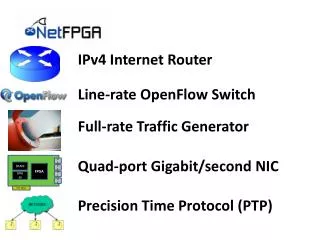
FPGA: What ? Why ?. Marco D. Santambrogio marco.santambrogio@polimi.it. Reconfigurable Hardware.

E N D
FPGA: What? Why? Marco D. Santambrogio marco.santambrogio@polimi.it
Reconfigurable Hardware “Reconfigurable computing is intended to fill the gap between hardware and software, achieving potentially much higher performance than software, while maintaining a higher level of flexibility than hardware” (K. Compton and S. Hauck, Reconfigurable Computing: a Survey of Systems and Software, 2002)
Evolution of implementation technologies • Logic gates (1950s-60s) • Regular structures for two-level logic (1960s-70s) • muxes and decoders, PLAs • Programmable sum-of-products arrays (1970s-80s) • PLDs, complex PLDs • Programmable gate arrays (1980s-90s) • densities high enough to permit entirely newclass of application, e.g., prototyping, emulation,acceleration trend toward higher levels of integration
Gate Array Technology (IBM - 1970s) • Simple logic gates • combine transistors toimplement combinationaland sequential logic • Interconnect • wires to connect inputs andoutputs to logic blocks • I/O blocks • special blocks at peripheryfor external connections • Add wires to make connections • done when chip is fabbed • “mask-programmable” • construct any circuit
Field-Programmable Gate Arrays • Logic blocks • to implement combinationaland sequential logic • Interconnect • wires to connect inputs andoutputs to logic blocks • I/O blocks • special logic blocks at peripheryof device for external connections • Key questions: • how to make logic blocks programmable? • how to connect the wires? • after the chip has been fabbed
Commercial FPGA Companies Lattice officialwebiste
Xilinx Programmable Gate Arrays • CLB - Configurable Logic Block • Built-in fast carry logic • Can be used as memory • Three types of routing • direct • general-purpose • long lines of various lengths • RAM-programmable • can be reconfigured
ConfigurableLogicBlocks • CLBsmade of Slices • sVirtex-E 2-slice • VIIP 4-slice • Slices made of LookUpTables (LUTs) • LookUpTables • 4-input, 1 output functions • Newest FPGA 2 6-input 2 output
Lookup Tables: LUTs 3 Inputs LUT -> 8 Memory Cells 3 – 6 Inputs Static Random Access Memory SRAM cells Multiplexer MUX LUT contains Memory Cells to implement small logic functions Each cell holds ‘0’ or ‘1’ . Programmed with outputs of Truth Table Inputs select content of one of the cells as output
The Virtex CLB 2-Slice Virtex-E CLB
Details of One Virtex Slice Virtex-E Slice
Implements any Two 4-input Functions 4-input function 3-input function; registered Virtex-E Slice
Y SLICE Switch Box TBUF SLICE_X66Y74 75 74 X 67 66 CLB 4-Slice VIIP CLB
Determine the configuration bits for the following circuit implementation in a 2x2 FPGA, with I/O constraints as shown in the following figure. Assume 2-input LUTs in each CLB. Example
Configuration Bitstream • The configuration bitstream must include ALL CLBs and SBs, even unused ones • CLB0: 00011 • CLB1: ????? • CLB2: 01100 • CLB3:XXXXX • SB0: 000000 • SB1: 000010 • SB2: 000000 • SB3: 000000 • SB4: 000001
The configuration bitstream • Occupation must be determined only on the basis of • Number of configuration words • Initial Frame Address Register (FAR) value
Frame and Configuration Memory • Virtex-II Pro • Configuration memory is arranged in vertical frames that are one bit wide and stretch from the top edge of the device to the bottom • Frames are the smallest addressable segments of the VIIP configuration memory space • all operations must act on whole configuration frames. • Virtex-4 • Configuration memory is arranged in frames that are tiled about the device • Frames are the smallest addressable segments of the V4 configuration memory space • all operations must therefore act upon whole configuration frames
Some Definitions • Object Code: the executable active physical (either HW or SW) implementation of a given functionality • Core: a specific representation of a functionality. It is possible, for example, to have a core described in VHDL, in C or in an intermediate representation (e.g. a DFG) • IP-Core: a core described using a HD Language combined with its communication infrastructure (i.e. the bus interface) • Reconfigurable Functional Unit: an IP-Core that can be plugged and/or unplugged at runtime in an already working architecture • Reconfigurable Region: a portion of the device area used to implement a reconfigurable core
FPGA EDA Tools • Must provide a design environment based on digital design concepts and components (gates, flip-flops, MUXs, etc.) • Must hide the complexities of placement, routing and bitstream generation from the user. Manual placement, routing and bitstream generation is infeasible for practical FPGA array sizes and circuit complexities.
Computer-aided Design • Can't design FPGAs by hand • way too much logic to manage, hard to make changes • Hardware description languages • specify functionality of logic at a high level • Validation - high-level simulation to catch specification errors • verify pin-outs and connections to other system components • low-level to verify mapping and check performance • Logic synthesis • process of compiling HDL program into logic gates and flip-flops • Technology mapping • map the logic onto elements available in the implementation technology (LUTs for Xilinx FPGAs)
CAD Tool Path (cont’d) • Placement and routing • assign logic blocks to functions • make wiring connections • Timing analysis - verify paths • determine delays as routed • look at critical paths and ways to improve • Partitioning and constraining • if design does not fit or is unroutable as placed split into multiple chips • if design it too slow prioritize critical paths, fix placement of cells, etc. • few tools to help with these tasks exist today • Generate programming files - bits to be loaded into chip for configuration