Download
1 / 14
140 likes | 291 Views
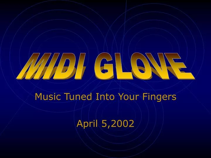
MIDI GLOVE. Music Tuned Into Your Fingers April 5,2002. Goals of Project. Create a glove that sends out signals based on finger position Use flex sensors, and an onboard MC Triangulate position of glove Use ultrasonics and Extended Kalman Filter

E N D
MIDI GLOVE Music Tuned Into Your Fingers April 5,2002
Goals of Project • Create a glove that sends out signals based on finger position • Use flex sensors, and an onboard MC • Triangulate position of glove • Use ultrasonics and Extended Kalman Filter • Translate X,Y,Z position and finger position into MIDI signals • Z-80 translates information into MIDI signals
Schematic Diagram 5 Flex Sensors (1 on each finger) COMPARATOR UHF Transmitter RB0–RB4 serial PIC MC Ultra-Sonic Transmitter RA0 Ultra-Sonic Receivers UHF Receiver serial Z-80 D0-D7 UART INT Stopwatch NMI INTA serial A0-A7 D0-D7 MIDI CTC Addressing
Software Flow Chart (Z-80) State Key Scale Stop Initialization GO C MJ 7-Segment Display Example Stop Menu Go Loop Scan Key Press 1 Key Press 2 Stop Set Key Set Scale Stop * Stop and Go is a flag that determines if MIDI signals are sent
Software Flow Chart (NMISR) NMISR : Non-Maskable Interrupt Service Routine Stop Test Flag Return Go From UART Finger Position Generate MIDI Code Send to UART
Software Flow Chart(IM1SR) IM1SR : Interrupt Mode 1 Service Routine Go Test Flag TimeValues From Ultrasonic Stop Calculate X Position Return Extended KalmanFilter Generate MIDI if necessary Send UART if necessary
Software Flow Chart (PIC) PIC PIC Interrupt Service Routine Initialization Button Press Send Signal To Z-80 Send Ultrasonic Sample flex sensor Return No Change State Change Change Send signal To Z-80
Parts List • Mattel Power Glove • (5) Flex Sensors • Ultrasonic Transmitter • (3) Ultrasonic Receivers • PIC 16F873 Microcontroller • (3) LP339 Quad Comparators • TX433 433.92MHz Transmitter • RX433 433.92MHz Receiver • Z-80 Microprocessor • 16550D UART • 8254 Counter Timer Circuit
Group Responsibilities • Andrew Howard • Integration • Adesina Bakare • MIDI Guru • Robert Zaretsky • Glove Hardware • Robert Ferreira • Software • Ryan Ferster • Triangulation
Current Status • Circuits designed • Triangulation equations derived • Glove with flex sensors and ultrasonics acquired • Other parts need to be ordered • Software in planning stage • Derivation of Extended Kalman Filter equations needed
Timeline for Project Phase • April 11 • Acquisition and implementation of circuits. • Start development of software. • April 18 • Integration circuits with glove, ultrasonics and RF transmitter/receiver. • Continued development of software • April 25 • Period allowed for testing and troubleshooting. • May 1 • Preparation for Demo.