Download

1 / 53
540 likes | 696 Views
MAC Layer Survey. The Medium Access Sublayer. MAC: Medium Access Control As opposed to “high access control” or “low access control”? NO! It means: controlling access to the medium. provides arbitration mechanism for shared medium What are arbitration mechanisms in this classroom?

E N D
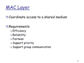
The Medium Access Sublayer • MAC: Medium Access Control • As opposed to “high access control” or “low access control”? • NO! • It means: controlling access to the medium. • provides arbitration mechanism for shared medium • What are arbitration mechanisms in this classroom? • Raising your hand • Verbal cues, e.g. “go ahead, Fred”. • Eye contact • Background: review of: • Broadcast vs. Point-to-Point media • Topologies: Bus, Ring • Then: Static vs. Dynamic channel allocation • Finally: ALOHA, and CSMA/CD (Ethernet)
typically use a “shared cable” typically are LAN technologies examples: Ethernet Cable Modems built from cables connecting single machines. often used to connect LANs into an internetwork (internet) Broadcast Networks vs. Point to Point networks • a special case: Token Ring • wiring is point to point, • but treated like broadcast
The Channel Allocation Problem (continued) • Statistical multiplexing is preferred to FDM and TDM. • Arrange all the packets in a giant central queue, and share the bandwidth on a first come first served basis. • Don’t pre-allocate bandwidth for users that may just waste it. • For details, need to review some basic queuing theory, and know what an exponential and poisson distribution are.
Dynamic channel allocation Five characteristics of channel allocation models: 1) Station model: stations independent 2) Single channel assumption 3) Collisions 4) Continuous (free-for-all, pure Aloha) vs Discrete Time (time is slotted) 5) Carrier sense (polite, listen first) vs. no Carrier Sense (just blurt out)
Aloha • 1970s Norman Abramson et. al, University of Hawaii • Send packets on shared channel; if collisions occur,wait random amount of time, and try again. • Original purpose: • host to terminal communication (very bursty) • ground-based radio channel; want to share it. • However, basic ideas have application to any environmentwhere there is a shared medium, and uncoordinated users • a bus-topology LAN • the up-link part of a Satellite channel
Pure (unslotted) • transmitwheneveryou like Time User User • Slotted • transmitat start ofnext slot • improvesefficiency,because thereare fewercollisions. =packet xmission A A B B C C D D E E =packet arrival Two variationsof Aloha
Forbidden region: frames that start in this region will collide. Efficiency of pure aloha... • When does frame X suffer no collisions? When there are no frames that overlap with frame X…i.e., only one frame starts in an interval of 2t. (Frames that start after t0 + 2t are ok).
Ethernet • Tannenbaum discussestwenty-eight of them! • some are abstract schemes • others are actual systems • So far, we’ve discussedfour abstract schemes • We’ll next briefly coverfour more abstract schemes Ethernet FDM Channel allocationmethods... TDM Pure ALOHA Slotted ALOHA 1-persistent CSMA Nonpersistent CSMA P-persistent CSMA CSMA/CD • then an actual product:that applies CSMA/CD:
Carrier Sense Multiple Access • Listen the channel before you transmit! • If the channel is busy don’t transmit; if it’s idle, transmit. • Most basic form: 1-persistent CSMA • If busy, listen persistently until channel is idle, then transmit immediately with probability 1. • Problem with 1-persistent CSMA: • Q: If any two stations B,C become “ready” during A’s transmission, what happens • A: guaranteed collision!
When station becomes ready (has a frame to send) User A • If busy, listen persistently until channel is idle B C Time Carrier Sense Multiple Access • Listen the channel before you transmit! • Most basic form: 1-persistent CSMA • Sense the channel first; if idle, transmit immediately. • then transmit immediately with probability 1.
User A B C Time Problem with 1-persistent CSMA Q: If any two stations B,C become “ready” during A’s transmission, what happens? A: Collision is guaranteed! • To address this problem, researchers have proposed: • non-persistent CSMA • p-persistent CSMA (for slotted channels).
non-persistent CSMA • if channel is busy, wait a random amount of time before sensing again. As an illustration, consider p=0.5, or equivalently, flipping a coin: tails: transmit heads: defer. A T B H C Time A T T B T C H T H Non-persistent and p-persistent CSMA p-persistent CSMA (for slotted channels). when idle, transmit with probability p; w/ prob (1-p), wait for next slot. Do we expect fewer collisions with these methods? What is the tradeoff?
Performance of CSMA protocols vs. Aloha • Tanenbaum doesn’t say where this analysis comes from, or what the assumptions are. But it does make the tradeoff clear: • less aggressive transmission means higher throughput, because there are fewer collisions, • but also higher delay!
User A B C Time Collision detection • All of the previous protocol (ALOHA, CSMA) assume collision = a total loss. • CSMA with Collision Detection (CSMA/CD) makes a different assumption: • we can detect a collision,and abort immediately, so we don’t waste an entire slot. • So, use 1-persistent CSMA, but if there is a collision, immediately stop, and wait a random period of time before trying again. • Ethernet and 802.3 use CSMA/CD.
Detecting collisions on a Bus network... • If is the maximum propagation time on a bus network, then it can take up to twice that long (2) for a collision to be detected. • This turns out to be a an important design parameter, as we will see.
If you need 2 to detect collisions... • … then you need to make sure that a frame isn’t shorter then 2 • Otherwise, a station might send an entire frame, and not realize that it had collided with something! • Thus, the minimum frame size in classic 10Mbps Ethernet = 64bytes. • What about 100Mbps Ethernet…? • If minimum frame size is the same, and bit rate is 10 times higher,and you still need 2 to detect collisions, then what must havechanged? • the maximum cable length has to be 10 times shorter.
Ethernet and 802.3 • Ethernet came first, invented at Xerox PARC (Palo Alto Research Center).(Bob Metcalfe was key figure; later went on to be a founder of 3COM.) • Xerox, Digital, and Intel were the “partners” in original commercial Ethernet spec. • Later, IEEE make 802.3 a standard • lots of variations at various bit rates using various media, • changed packet type field to a length field. (packet type values are all illegal lengths, so its easy to distinguish) • For most purposes of our discussion, we’ll consider them one and the same, although purists would insist that they are different standards.
802.3 Collision Detection is analog process • Station must read voltage on wire to see if it is the same aswhat the station is sending out. • Collision of two “0 volt signals” would be hard to detect! • This is a motivation for Manchester Encoding…Voltage is either 0.85 or -0.85, so if you add two signals together, with very high probability you will get an illegal voltage within a few bits.
Ethernet “dominant” LAN technology: • cheap $20 for 100Mbs! • first widely used LAN technology • Simpler, cheaper than token LANs and ATM • Kept up with speed race: 10, 100, 1000 Mbps Metcalfe’s Ethernet sketch
Ethernet Frame Structure Sending adapter encapsulates IP datagram (or other network layer protocol packet) in Ethernet frame Preamble: • 7 bytes with pattern 10101010 followed by one byte with pattern 10101011 • used to synchronize receiver, sender clock rates
Ethernet Frame Structure (more) • Addresses: 6 bytes, frame is received by all adapters on a LAN and dropped if address does not match • Type: indicates the higher layer protocol, mostly IP but others may be supported such as Novell IPX and AppleTalk) • CRC: checked at receiver, if error is detected, the frame is simply dropped
Ethernet: uses CSMA/CD A: sense channel, if idle then { transmit and monitor the channel; If detect another transmission then { abort and send jam signal; update # collisions; delay as required by exponential backoff algorithm; goto A } else {done with the frame; set collisions to zero} } else {wait until ongoing transmission is over and goto A}
Ethernet’s CSMA/CD (more) Jam Signal: make sure all other transmitters are aware of collision; 48 bits; Exponential Backoff: • Goal: adapt retransmission attemtps to estimated current load • heavy load: random wait will be longer • first collision: choose K from {0,1}; delay is K x 512 bit transmission times • after second collision: choose K from {0,1,2,3}… • after ten or more collisions, choose K from {0,1,2,3,4,…,1023}
Ethernet Technologies: 10Base2 • 10: 10Mbps; 2: under 200 meters max cable length • thin coaxial cable in a bus topology • repeaters used to connect up to multiple segments • repeater repeats bits it hears on one interface to its other interfaces: physical layer device only!
10BaseT and 100BaseT • 10/100 Mbps rate; latter called “fast ethernet” • T stands for Twisted Pair • Hub to which nodes are connected by twisted pair, thus “star topology”
LAN Addresses and ARP 32-bit IP address: • network-layer address • used to get datagram to destination network (recall IP network definition) LAN (or MAC or physical) address: • used to get datagram from one interface to another physically-connected interface (same network) • 48 bit MAC address (for most LANs) burned in the adapter ROM
LAN Addresses and ARP Each adapter on LAN has unique LAN address
LAN Address (more) • MAC address allocation administered by IEEE • manufacturer buys portion of MAC address space (to assure uniqueness) • Analogy: (a) MAC address: like Social Security Number (b) IP address: like postal address • MAC flat address => portability • can move LAN card from one LAN to another • IP hierarchical address NOT portable • depends on network to which one attaches
223.1.1.1 223.1.2.1 E B A 223.1.1.2 223.1.2.9 223.1.1.4 223.1.2.2 223.1.3.27 223.1.1.3 223.1.3.2 223.1.3.1 Recall earlier routing discussion Starting at A, given IP datagram addressed to B: • look up net. address of B, find B on same net. as A • link layer send datagram to B inside link-layer frame frame source, dest address datagram source, dest address A’s IP addr B’s IP addr B’s MAC addr A’s MAC addr IP payload datagram frame
Question: how to determine MAC address of B given B’s IP address? ARP: Address Resolution Protocol • Each IP node (Host, Router) on LAN has ARP module, table • ARP Table: IP/MAC address mappings for some LAN nodes < IP address; MAC address; TTL> < ………………………….. > • TTL (Time To Live): time after which address mapping will be forgotten (typically 20 min)
ARP protocol • A knows B's IP address, wants to learn physical address of B • A broadcasts ARP query pkt, containing B's IP address • all machines on LAN receive ARP query • B receives ARP packet, replies to A with its (B's) physical layer address • A caches (saves) IP-to-physical address pairs until information becomes old (times out) • soft state: information that times out (goes away) unless refreshed
Routing to another LAN walkthrough: routing from A to B via R • In routing table at source Host, find router 111.111.111.110 • In ARP table at source, find MAC address E6-E9-00-17-BB-4B, etc A R B
A creates IP packet with source A, destination B • A uses ARP to get R’s physical layer address for 111.111.111.110 • A creates Ethernet frame with R's physical address as dest, Ethernet frame contains A-to-B IP datagram • A’s data link layer sends Ethernet frame • R’s data link layer receives Ethernet frame • R removes IP datagram from Ethernet frame, sees its destined to B • R uses ARP to get B’s physical layer address • R creates frame containing A-to-B IP datagram sends to B A R B
Bridges, Internetworking • Before talking about bridges in the context of the MAC sub-layer, lets briefly skip ahead, and cover the differences among: gateways routers bridges repeaters
host host A A T T N N D D mac mac Ph Ph Repeater Repeaters • Copy individual bits between cable segments, and that is all. • Operate at physical layer only.
host host A A T T N N bridge D D D mac mac mac mac Ph Ph Ph Ph Bridges • Operate at Data link layer, and may connect two similar LANs,or two dissimilar, but at least partially compatible LANs. • For dissimilar LANs (e.g. 802.x to 802.y, where xy)differences in frame size, priority schemes, etc. create headachesand incompatibilities.
host A host T A router N T D N N mac D D D Ph mac mac mac Ph Ph Ph Routers • Operate at Network layer. Usually connect two networks using same network layer. • Tanenbaum discusses “multiprotocol routers”; • Often these connect two networks that have multiple network protocols, but don’t do conversions from one to another.(This is how I have seen them used.) • Tanenbaum implies: sometimes they convert from one network layer to another.
host A gateway host T A A N T T T D N N N mac D D D Ph mac mac mac Ph Ph Ph Gateways • Operate at Transport and/or Application Layer • Examples: • a gateway between Internet (TCP/IP) SMTP-based email and a proprietary email system like IBM’s “PROFS” (based on SNA) or Digital’s (DECs) “All-in-one” or VAX/VMS Mail (based on DECnet). • a gateway between SNA’s 3270 terminals and TCP/IP Telnet style terminal sessions. • Proxy server
gateway host host A A A router T T T T N N N N N host host host host host D D m m A A A A Ph Ph Ph Ph Ph A Ph T T T T T N N N N host N bridge A D D D D D D T m m m m m N m m D D D D D repeater Ph Ph Ph Ph m m m m m Ph Ph Ph Ph Ph Ph Summary: Repeaters, Bridges, Routers, Gateways • The distinction lies mainly in the “highest” layer at which each operates. • Although this terminology is fairly standard, and the preferred common usage, the term “gateway” is sometimes used in the Internet community as a synonym for “router”. (for example, in the name of the “Exterior Gateway Protocol”.) • Now let’s turn our attention back to a possibly confusing questions about bridges… • do bridges do routing?
Ethernet Bridges for collisions/noise/trafficeach segment looks like a separate Ethernet BUT, for forwarding frames to destination Ethernet addresses the entire network seems to bea single large Ethernet The bridges handle routing Ethernet Repeaters each segment can be 500m no more than 4 repeatersbetween any two computers maximum distance 2500m a 10BaseT hub countsas a repeater. segment 2 on floor 3 segment 1 on floor 3 vertical segment segment 2 on floor 2 segment 1 on floor 2 segment 2 on floor 1 segment 1 on floor 1 LAN 2 LAN 1 u v w x y z
LAN 6 LAN 3 LAN 4 LAN 5 Bridges can connect more than one LAN • We can build an extended LAN by connecting up smaller LANs through bridges • Goal: • (LAN3, LAN4, LAN5, LAN6)separate for collisions, local traffic • (LAN3, LAN4, LAN5, LAN6)all one LAN for sending, addressing • Bridges functions as data-link layer routers • Routing tables are self-configuring. Four (equiv.) names for this: • adaptive bridges – backwards-learning bridges • learning bridges – transparent bridges
segment 2 segment 1 u v w x y z How adaptive bridges learn seg. 2 seg. 1 • The bridge B has this goal: only forward frames when necessary! • don’t forward local traffic between hosts on seg. 1 to seg. 2, and vice-versa • e.g., traffic between u and w should stay local to seg. 1 • How is this achieved? • At first forwarding every incoming frame onto every destination lan (flooding) • As the bridge “learns” where hosts are, it only forwards the frame if necessary. • How does it learn where hosts “live”? By “backward learning” • We figure out the destination seg. for packets going to y, by looking at the source seg. for packets coming fromy.
LAN 6 LAN 3 LAN 4 LAN 5 LAN 2 LAN 1 u v w x y z Startup/Steady State LAN 2 LAN 1 • The startup behavior is to forward every frame everywhere (flooding) • The steady state is to forward frames ONLY where they belong.
Do Bridges Do Routing?Where the confusion can arise... • In discussing bridge design, we may talk about “routing tables” in the bridges and how “routing” is done. • e.g. sending a frame DA vs. DC vs. DH. • We’re talking about routings packets at the Data Link Layer through an interconnection of LAN segments that make up an “extended LAN”. • This is similar in function (in some ways) to routing at the network layer, but it is NOT the network layer; the network layer sits “above” all this.
Planning A Bridged Network • Bridges allow parallelism, and isolate traffic. • Simultaneously: (AB) (ED) (FH) without any collision. • Exploit “locality of reference”; idea is that most accesses are to • local file servers • local printers • So put users of a server/printer on the same bridged segment • keep local traffic local
Bridging Between Buildings:Goal is to keep local traffic local! building 1 building 2 Ethernet Ethernet optical fibers Bad: Traffic from both sides goes across the fiber optic link fiber modem fiber modem Good: local trafficstays local building 2 building 1 bridge optical fibers between buildings fiber modem fiber modem
Bridging Across Longer Distances: Keep local traffic off the long-distance link satellite LAN 2 LAN 1 bridge bridge
A Cycle Of Bridges • In transparent bridging: the idea is, you just plug and play • the bridges configure themselves! • but what if you put in a cycle? • What will happen?
Problems with a cycle of bridges • The fear: • more than one bridge may forward a frame, creating wasteful duplicates • loops may cause frames to be forwarded forever • Example: • Suppose that frame F is going to an “unknown” destination, • Both bridge B1 and bridge B2 use flooding (send it everywhere) • Now what happens when B1 sees frame F2, and B2 sees frame F1? • They will forward it back to LAN1, creating frames F3 and F4… • etc. etc. etc.