Download
1 / 31
310 likes | 444 Views
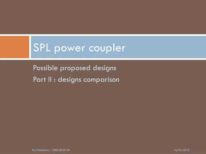
SPL power coupler. Possible proposed designs Part II : designs comparison. Summary. Comparison of proposed designs: SPL-CEA coaxial disk water cooled window SPL-SPS coaxial disk air cooled window SPL-LHC cylindrical air cooled window Design issues Waveguides Titanium coating

E N D
SPL power coupler Possible proposed designs Part II : designs comparison Eric Montesinos / CERN-BE-RF-SR
Summary • Comparison of proposed designs: • SPL-CEA coaxial disk water cooled window • SPL-SPS coaxial disk air cooled window • SPL-LHC cylindrical air cooled window • Design issues • Waveguides • Titanium coating • RF simulations • Coupling box • Construction process • Conditioning process • Mass production • New proposed schedule • Conclusion Eric Montesinos / CERN-BE-RF-SR
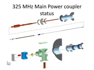
Three possible remaining designs • All use the same double walled tube • All use the same vacuum gauge, electron monitor and arc detector • We have designed them to be compatible without modifying the cryomodule Eric Montesinos / CERN-BE-RF-SR
Three possible remaining designs • SPL-CEA HIPPI coaxial disk water cooled window • SPL-SPS coaxial disk air cooled window • SPL-LHC cylindrical air cooled window Eric Montesinos / CERN-BE-RF-SR
Coaxial disk water cooled window • CEA design based on a coaxial disk ceramic window as in operation at KEKB and SNS, modified for 704MHz • Advantages • High power capability, tested up to 1MW with 2ms / 50Hz on warm test cavity and on cold cavity last week • Matched window, this allows to easily change the waveguide position • Commercially produced window (Toshiba) • Drawbacks • Window and antenna are water cooled: • Not following CERN vacuum group recommendations • Needs accurate mounting • Difficult DC HV biasing due to water: • Need insulating pipes (X-rays, radiation,... More maintenance and operational costs) • Need a second air cooling circuit for the waveguide: • Doubles the operational needs: water and air systems Waveguide air cooling Antenna and outer ceramic water cooling Eric Montesinos / CERN-BE-RF-SR
Coaxial disk water cooled window • Quite complex brazing process (compare to SPS and LHC) • Water seal to be modified from organic (acceptable for test) to metallic (for long term operation without maintenance) • the tolerances are very tight • No flexibility for the antenna: • Stress to the ceramic • RF contact depends on tolerances • Possible water leak if misalignment (already happened) Eric Montesinos / CERN-BE-RF-SR
Coaxial disk air cooled window • Design based on a coaxial disk ceramic window similar as the one in operation on the CERN SPS TWC 200MHz power load • Advantages • Very simple and well mastered brazing of ceramic onto a titanium flange • High power capability (500kw cw) • Very easy to cool with air • Waveguide as “plug and play” mounting, absolutely no stress to the antenna • DC HV biasing very simple, with again a “plug and play” capacitor fitting, and again no stress to the ceramic due to finger contact • Least expensive of the three couplers ! • Minor drawback • Ceramic is part of the matching system, fixes the waveguide position Ceramic and waveguide air cooling Antenna and outer ceramic air cooling Eric Montesinos / CERN-BE-RF-SR
Coaxial disk air cooled window • Very simple brazing process: • Titanium outer flange: • Dilatation coefficient near ceramic • Surface hard enough for vacuum copper seals • Inner tube in copper 1.2mm thickness to allow easy brazing • Antenna inner upper part has been designed: • With spring washers for a good RF contact between the upper and lower inner conductor sections • Without any stress to the ceramic • Allowing a correct air flow SPS Window: very simple brazing process Spring washers Air “cane” RF contact RF contact without stress to the ceramic by compression of the outer line through the air “cane” Eric Montesinos / CERN-BE-RF-SR
“Plug and play” waveguide system • Need additional 50 Ωouter lines: • Vacuum side for monitoring vacuum, electron, light, … • Air side for RF matching and for air cooling of the ceramic • “Plug and play” waveguide and biasing capacitor • There is a finger contact all around the capacitor to avoid stress on the ceramic • This waveguide mounting method has already been used successfully for the LHC couplers Eric Montesinos / CERN-BE-RF-SR
Cylindrical air cooled window • Design based on the same cylindrical window as the LHC couplers: • Long and difficult process to achieve reliability of the window, the final design was obtained after more than six years of studies • As the design was complex, we keep it exactly as it is • Instead of changing the ceramic design we have adapted the line to the ceramic • Advantages • High power capability window, LHC proven (575kW cw full reflection, could be more…) • Simple to cool with air • Absolutely free of mechanical stress on the antenna • Same “plug and play” waveguide and DC capacitor as previous design, no stress to the ceramic • Simplest version to assemble ! • Drawbacks • Ceramic is part of the matching system, fixes the waveguide position • Possible multipacting due to the outer conical outer line Ceramic and waveguide air cooling Eric Montesinos / CERN-BE-RF-SR
Cylindrical air cooled window • LHC window is a huge improvement over the LEP window, with less losses and higher power capability • We still not know the upper power limit of the LHC window • The LHC coupler were powered up to 575kW cw full reflection (SW) for several hours all phases • Klystrons failed, not the coupler ! • The LHC window appears to be really robust • To date 30 LHC couplers have been built and tested, 16 are in operation in LHC • A new coupler using exactly the same ceramic window is under construction for ESRF and SOLEIL → Standardization of the ceramic ESRF-LHC new design LHC window: Two solid copper collars brazed to the ceramic First EB welding (mechanical) Third EB welding (mechanical and vacuum) Second EB welding (mechanical and vacuum) Eric Montesinos / CERN-BE-RF-SR
“Plug and play” waveguide system • Same “Plug and play” waveguide and biasing capacitor as with the coaxial air cooled window • The waveguide has just one contact with the body line • There is a finger contact all around the capacitor to avoid stress on the ceramic Eric Montesinos / CERN-BE-RF-SR
Comparison: Titanium coating • LHC, coating done twice: • First coating on the top and the bottom edges of the ceramic (electrical continuity) • Brazing of the copper collars • Second coating on the inside of the ceramic • → Double the costs • SPS, only one coating: • Straight forward • Done after brazing • Toshiba process: • Probably one coating • What about the part of ceramic masked by the chokes? First coating: R = 0.5 MΩ Second coating: R = 2 MΩ One coating: R = 2 MΩ ? What about the part of ceramic behind the choke ? One coating: R = 2 MΩ Eric Montesinos / CERN-BE-RF-SR
Comparison: S11 simulations Cavity bandwidth 704 MHz / Qext (1.2 x 10⁶) = 586 Hz SPL-CEA SPL-LHC SPL-SPS Eric Montesinos / CERN-BE-RF-SR
Comparison: Field Strength SPL-CEA Max 751 kV/m with 1MW SPL-SPS SPL-LHC Max 880 kV/m with 1MW Max 866 kV/m with 1MW Eric Montesinos / CERN-BE-RF-SR
Waveguides options • If needed, LHC design could be done with a “coaxial conical” extension line to change the waveguide position • We simulated the waveguide with steps to check effects on the field distribution, it reduces the field strength • Using a waveguide without doorknob considerably eases the mounting and reduces the cost (as LHC) • Immediately after the coupler waveguide flange, there will be a flexible waveguide to reduce mechanical stresses • Nevertheless, a supporting tool will be necessary for the coupler waveguide, still to be studied LHC design with a possible conical coaxial extension to change the waveguide axis Two steps waveguide: slightly reduces the field strength Doorknob / reduced height: ~ same field strength Eric Montesinos / CERN-BE-RF-SR
Comparison Eric Montesinos / CERN-BE-RF-SR
Coupling box • Will be used to: • Connect two couplers in the vertical position for conditioning • Storage and transport chamber with springs to damp shocks • Solid copper: • Low RF losses • Strong enough to sustain deformation due to strong pressure effects • Extra external mechanical adjustment for frequency tuning • Could be EB soldered or assembled from two parts: • Vacuum seal • Easy to clean, we want to re-use it for 250 couplers ! Springs to avoid any shock while transporting Eric Montesinos / CERN-BE-RF-SR
Vacuum leak detections after each major operation Construction process • We plan to follow an upgraded LHC coupler construction process: • Build all components: • Metrologic controls • Mechanical and thermal tests • In clean room (class 100): • clean all parts in contact with beam vacuum with pure water or pure alcohol • Particle counting to validate the cleaning • In clean room (class10): • assemble a pair of couplers and mount them on a test cavity • Bake out • RF conditioning • In clean room (class 10): mounting of coupler with its double walled tube on SPL cavity Eric Montesinos / CERN-BE-RF-SR
Construction process • To be carefully followed-up: • Assembly tooling • Handling with special gloves only, avoid contamination of surfaces by hydrocarbons, finger prints,… • Optimize the process to minimize the number of handlings • Avoid intermediate packing in polymeric sealed bags (contamination) • Specially designed transport containers • Visit tomorrow of the three facilities: • Building 252 class 100 clean room • Building 252 class 10 clean room • Building SM18 class 10 clean room • Would like advice on what we could improve for high gradient cavities Eric Montesinos / CERN-BE-RF-SR
Conditioning process • Install one cavity with its two power couplers and prepare for conditioning • List of interlocks and monitoring: • Vacuum gauges • Directional couplers • Light detector • Electron monitor • Thermal measurements • Gas analyzer • Air flow meter • Water flow meter (power load) • … • The tests will be done at CEA Saclay TTF III power coupler test bench Eric Montesinos / CERN-BE-RF-SR
Conditioning process • The conditioning loop will be the same as the one used since 1998 with the SPS and LHC couplers: • A first direct vacuum loop (red) ensures RF is never applied if pressure exceeds 5.0 x 10⁻⁷ mbar • A second vacuum loop (blue), cpu controlled, executes the automated process • The interlock vacuum threshold of 5.0 x 10⁻⁷ mbar will be chosen, guided by our experience, to protect the couplers, but also to have an as short as possible conditioning time • The settings are adjusted to have minimum attenuation under 1.0 x 10⁻⁸ mbar and maximum attenuation over 2.5 x 10⁻⁷ mbar (~40 dB dynamic range with the attenuator) Eric Montesinos / CERN-BE-RF-SR
Conditioning process • The conditioning process will be similar to the LHC one: • The process always starts, under vacuum control, with very short pulses of 20 µs every 20 ms • Power level is increased using short pulses up to full power passing slowly through all power levels to avoid “de-conditioning” • Same procedure repeated for initially short then longer and longer pulses up to the maximum length • The conditioning process will be considered finished when the vacuum level decreases below a predefined level (1 x 10⁻⁸ mbar for example), while ramping the maximum length pulse Eric Montesinos / CERN-BE-RF-SR
Double walled tube rough estimate: 15’000 CHFCoupling box rough estimate: 25’000 CHF Eric Montesinos / CERN-BE-RF-SR
SPL-CEA rough estimate:53’000 CHF Eric Montesinos / CERN-BE-RF-SR
SPL-SPS rough estimate:27’000 CHF Eric Montesinos / CERN-BE-RF-SR
SPL-LHC rough estimate:30’000 CHF Eric Montesinos / CERN-BE-RF-SR
Mass production Eric Montesinos / CERN-BE-RF-SR
New proposed schedule • Integrate advice and launch as soon as possible: • One pair of coaxial air cooled window • One pair of cylindrical air cooled window • Have 2 pairs ready for tests beginning 2011 • Decide which ones to construct in March 2011 (still three possible choices) • Construct remaining couplers in 2011 • Have 8 fully ready and conditioned couplers beginning 2012 Today: coupler review Confirm the Saclay test stand availability in 2011: February and end of year? Eric Montesinos / CERN-BE-RF-SR
Conclusion: still a lot to do… • Eight couplers could be ready within two years: • Necessarily based on existing designs and very well known processes • Coaxial air cooled and cylindrical air cooled versions to be tried: • Potentially inexpensive for mass production • Interesting for large machines • Keep the coaxial water cooled option open: • Study the modification of the cooling from water to air • Redesign the waveguide transition for: • Less stress to the ceramic • Easier DC biasing Eric Montesinos / CERN-BE-RF-SR
Many thanks for your patience Eric Montesinos / CERN-BE-RF-SR