Download
1 / 21
210 likes | 374 Views
Scaling Internet Routers Using Optics. Isaac Keslassy, et al. Proceedings of SIGCOMM 2003. Slides: http://tiny-tera.stanford.edu/~nickm/talks/Sigcomm_2003.ppt. Do we need faster routers?. Traffic still growing 2x every year Router capacity growing 2x every 18 months

E N D
Scaling Internet Routers Using Optics Isaac Keslassy, et al. Proceedings of SIGCOMM 2003. Slides: http://tiny-tera.stanford.edu/~nickm/talks/Sigcomm_2003.ppt applied research laboratory
Do we need faster routers? • Traffic still growing 2x every year • Router capacity growing 2x every 18 months • By 2015, there will be a 16x disparity • 16 times the number of routers • 16 times the space • 256 times the power • 100 times the cost • => Necessity for faster, cost effective, space and power efficient routers. Source: Dr. Nick McKeown’s SIGCOMM talk applied research laboratory
Current router : Juniper T640 • T640: Half-rack • 37.45 x 17.43 x 31 in (H x W x D) • 95.12 x 44.27 x 78.74 cms (area ≈ 3 m2) • 32 interface card slots • 640 Gbps front side switching capacity • 6500 W power dissipation • Black body radiation = T4 W/m2 • at 350 F, Power radiated = 2325 W/m2 • Operating temp. = 32 to 104 F = 0 to 40 C • = Stefan Boltzmann constant = 5.670 * 10-8 W / m2 K4 • References: • http://www.alcatel.com/products/productCollateralList.jhtml?productRepID=/x/opgproduct/Alcatel_7670_RSP.jhtml • http://www.juniper.net/products/ip_infrastructure/t_series/100051.html#03 • http://www.cisco.com/en/US/products/hw/routers/ps167/products_data_sheet09186a0080092041.html applied research laboratory
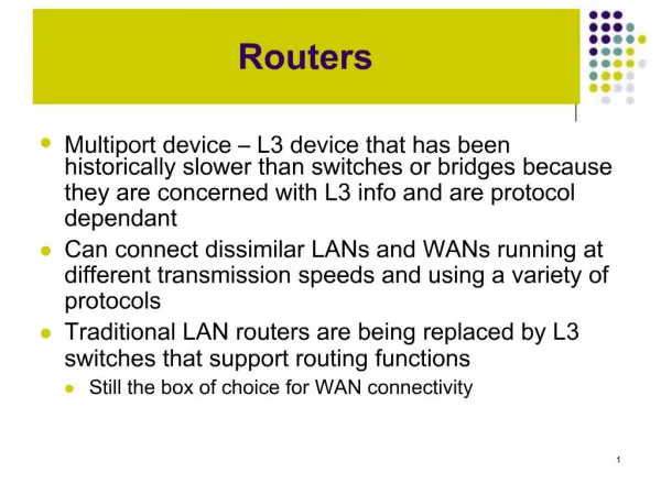
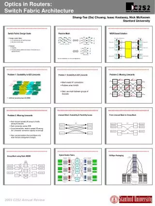
Multi-rack routers • Switch fabric and linecards on separate racks • Problem: Switch fabric power density is limiting • Limit = 2.5 Tbps (scheduler, opto-electronic conversion, other electronics) • Switch fabric can be single stage or multi stage • Single stage: complexity of arbitration algorithms • Multi-stage: unpredictable performance (unknown throughput guarantees) Switch fabric Linecards applied research laboratory
Optical switch fabric • Pluses • huge capacity • bit rate independent • low power • Minuses • slow to configure (MEMS ≈ 10 ms) • fast switching fabrics based on tunable lasers are expensive • Reference: • http://www.lightreading.com/document.asp?doc_id=2254&site=lightreading applied research laboratory
Goals • Identify architectures with predictable throughput and scalable capacity • Use the load balanced switch described by C-S. Chang • Find practical solutions to the problems with the switch when used in a realistic setting • Use optics with negligible power consumption to build higher capacity single rack switch fabrics (100 Tbps) • Design a practical 100 Tbps switch with 640 linecards each supporting 160 Gbps applied research laboratory
Load balanced switch • 100 % throughput for a broad class of traffic • No scheduler => scalable VOQ VOQ VOQ applied research laboratory
Problems with load-balanced switch • Packets can be mis-sequenced • Pathological traffic patterns can make throughput arbitrarily small • Does not work when some of the linecards are not present or are have failed • Requires two crossbars that are difficult or expensive to implement using optical switches applied research laboratory
Linecard block diagram • Both input and output blocks in one linecard • Intermediate input block for the second stage in the load balanced switch applied research laboratory
Switch reconfigurations • The crossbars in the load balanced switch can be replaced with a fixed mesh of N2 links each of rate R/N • The two meshes can be replaced with a single mesh carrying twice the capacity (with packets traversing the fabric twice) R R R R/N R/N R 2R/N applied research laboratory
Optical switch fabric with AWGRs • AWGR: data-rate independent passive optical device that consumes no power • Each wavelength operates at rate 2R/N • Reduces the amount of fiber required in the mesh (N2) • N = 64 is feasible but N = 640 is not AWGR = Arrayed Wavelength Grating Router applied research laboratory
Decomposing the mesh 2R/8 1 1 2 2 3 3 4 4 5 5 6 6 7 7 8 8 Source: Dr. Nick McKeown’s SIGCOMM slides applied research laboratory
WDM TDM Decomposing the mesh 1 2R/8 2R/8 1 2R/4 2R/8 2R/8 2 2 3 3 4 4 5 5 6 6 7 7 8 8 Source: Dr. Nick McKeown’s SIGCOMM slides applied research laboratory
Full Ordered Frames First (FOFF) • Every N time slots • Select a queue to serve in round robin order that holds more than N packets • If no queue has N packets, pick a non-empty queue in round robin order • Serve this queue for the next N time slots N FIFO queues (one per output) To intermediate input block input applied research laboratory
FOFF properties • No Mis-sequencing • Bounds the amount of mis-sequencing inside the switch • Resequencing buffer at most N2 + 1 packets • FOFF guarantees 100 % throughput for any traffic pattern • Practical to implement • Each stage has N queues, first and last stages hold N2+1 packets/linecard • Decentralized and does not need complex scheduling • Priorities are easy to implement using kN queues at each linecard to support k priority levels applied research laboratory
Flexible linecard placement • When second linecard fails, links between first and second linecards have to support a rate of 2R/2 • Switch fabric must be able to interconnect linecards over a range of rates from 2R/N to R => Not practical 2R/3 applied research laboratory
Partitioned switch • Theorems: • M = L+G-1, each path supporting a rate of 2R • Polynomial time reconfiguration when new linecards are added or removed. M input/output channels for each linecard applied research laboratory
M = L + G -1 illustration • Total traffic going out or coming in at Group 1 = LR • Total number of linecards = L + G -1 • Number of extra paths needed to/from first group = L -1 Group 1 Group 1 LC 1 LC 1 LC 2 LC 2 LC L LC L Group 2 Group 2 LC 1 LC 1 Group G Group G LC 1 LC 1 applied research laboratory
Hybrid electro-optical switch applied research laboratory
Optical Switch applied research laboratory
40 x 40 MEMS Linecard Rack 1 Linecard Rack G = 40 Switch Rack < 100W L = 16 160Gb/s linecards L = 16 160Gb/s linecards 1 2 55 56 100Tb/s Load-Balanced Router L = 16 160Gb/s linecards Source: Dr. Nick McKeown’s SIGCOMM slides applied research laboratory