Download
1 / 22
220 likes | 353 Views
FIGURE OF MERIT FOR MUON IONIZATION COOLING. Ulisse Bravar University of Oxford 28 July 2004. 100 m cooling channel. Channel structure from Study II Cooling: d e ^ / dx = -e ^ /l + e ^, equil. / l

E N D
FIGURE OF MERIT FOR MUON IONIZATION COOLING Ulisse Bravar University of Oxford 28 July 2004
100 m cooling channel • Channel structure from Study II • Cooling: de^ / dx = -e^/l + e^,equil./l • Goal: 4-D cooling. Reduce transverse emittance from initial value e^ to e^,equil. • Accurate definition and precise measurement of emittance not that important
MICE • Goal: measure small effect with high precision, i.e.De^/e^ ~ 10% to 10-3 • Full MICE (LH + RF) • Empty MICE (no LH, RF) • Software: ecalc9f • De^/e^ does not stay constant in empty channel
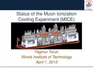
The MICE experiment The MICE experiment • Measure a change in e4 with an accuracy of 10-3. • Measurement must be precise !!! Coupling Coils 1&2 Spectrometer solenoid 1 Matching coils 1&2 Matching coils 1&2 Spectrometer solenoid 2 Focus coils 1 Focus coils 2 Focus coils 3 m Beam PID TOF 0 Cherenkov TOF 1 RF cavities 1 RF cavities 2 Downstream particle ID: TOF 2 Cherenkov Calorimeter Diffusers 1&2 Liquid Hydrogen absorbers 1,2,3 Incoming muon beam Trackers 1 & 2 measurement of emittance in and out
Quantities to be measured in MICE cooling effect at nominal input emittance ~10% Acceptance: beam of 5 cm and 120 mrad rms equilibrium emittance = 2.5 p mm rad
Emittance measurement Each spectrometer measures 6 parameters per particle x y t x’ = dx/dz = Px/Pz y’ = dy/dz = Py/Pz t’ = dt/dz =E/Pz Determines, for an ensemble (sample) of N particles, the moments: Averages <x> <y> etc… Second moments: variance(x)sx2 = < x2 - <x>2 > etc… covariance(x)sxy = < x.y - <x><y> > Covariance matrix M = Getting to e.g. sx’t’ is essentially impossible with multiparticle bunch measurements Compareein witheout Evaluate emittance with:
Emittance in MICE (1) • Trace space emittance: etr ~ sqrt (<x2> <x’2>) (actually, etr comes from the determinant of the 4x4 covariance matrix) • Cooling in RF • Heating in LH • Not good !!!
Emittance in MICE (2) • Normalised emittance (the quantity from ecalc9f): • e^ ~ sqrt (<x2> <px2>) (again, from the determinant of the 4x4 covariance matrix) • Normalised trace space emittance etr,norm ~ (<pz>/mmc) sqrt (<x2> <x’2>) • The two definitions are equivalent only when spz = 0 (Gruber 2003) !!! • Expect large spread in pzin cooling channel
Muon counting in MICE • Alternative technique to measure cooling: • fix 4-D phase space volume • count number of muons inside that volume • Solid lines number of muons in x-px space increases in MICE • Dashed lines number of muons in x-x’ space decreases Use x-px space !!!
Emittance in drift (1) • Problem: Normalised emittance increases in drift (e.g. Gallardo 2004) • Trace space emittance stays constant in drift (Floettmann 2003)
Emittance in drift (2) • x-px correlation builds up: initialfinal Emittance increase can be contained by introducing appropriate x-px correlation in initial beam
Emittance in drift (3) • Normalised emittance in drift stays constant if we measure e^ at fixed time, not fixed z • For constant e, we need linear eqn. of motion: a) normalised emittance: x2 = x1 + t dx/dt = x1 + t px/m b) trace space emittance: x2 = x1 + z dx/dz = x1 + z x’ • Fixed t not very useful or practical !!!
Solenoidal field • Quasi-solenoidal magnetic field: Bz = 4 T within 1% • Initial b^ within 1% of nominal value b^ fluctuates by less than 1 %
Emittance in a solenoid (1) • Normalised 4x4 emittance – ecalc9f • Normalised 2x2 emittance • Normalised 4x4 trace space emittance • Normalised 2x2 emittance with canonical angular momentum
Muon counting in a solenoid • In a solenoid, things stay more or less constant • This is 100% true in 4-D x-px phase space solid lines • Approximately true in 4-D x-x’ trace space dashed lines
Emittance in a solenoid (2) • Use of canonical angular momentum: px px + eAx/c, Ax = vector potential to calculate e^ • Advantages: a) Correlation sx,y’ = s1,4 << 1 b) 2-D emittance exx’ ~ constant • Note: Numerically, this is the same as subtracting the canonical angular momentum L introduced by the solenoidal fringe field • Usually sx,y’ = s1,4 in 4x4 covariance matrix takes care of this 2nd order correlation • We may want to study 2-D ex and ey separately… see next page !!!
MICE beam from ISIS • Beam in upstream spectrometer • Beam after Pb scatterer y y x
How to measure e^ (1) • Standard MICE • MICE with LH but no RF • Mismatch in downstream spectrometer • We are measuring something different from the beam that we are cooling !!!
How to measure e^ (2) • Spectrometers close to MICE cooling channel • Spectrometers far from MICE cooling channel with pseudo-drift space in between • If spectrometers are too far apart, we are again measuring something different from the beam that we are cooling !!! e^ increase in “drift”
Quick fix: x – px correlation Close spectrometers Far spectrometers Far spectrometers with x-px correlation
Gaussian beam profiles • Real beams are non-gaussian • Gaussian beams may become non-gaussian along the cooling channel • When calculating e^ from 4x4 covariance matrix, non-gaussian beams result in e^ increase • Can improve emittance measurement by determining the 4-D phase space volume • In the case of MICE, may not be possible to achieve 10-3 • Cooling that results in twisted phase space distributions is not very useful
Conclusions • Use normalised emittance x-px as figure of merit • Accept increase in e^ in drift space • Consider using 2-D emittance with canonical angular momentum • Make sure that the measured beam and the cooled beam are the same thing • Do measure 4-D phase space volume of beam, but do not use as figure of merit