Download
1 / 34
350 likes | 481 Views
Status on long-wavelength InP waveguide heterojunction phototransistors. Samuel Dupont, Vincent Magnin, Manuel Fendler, Filippe Jorge, Sophie Maricot, Jean-Pierre Vilcot, Joseph Harari, Didier Decoster Institut d'Electronique de Microélectronique et de Nanotechnologie , UMR CNRS 8520

E N D
Status on long-wavelength InP waveguide heterojunction phototransistors Samuel Dupont, Vincent Magnin, Manuel Fendler, Filippe Jorge, Sophie Maricot, Jean-Pierre Vilcot, Joseph Harari, Didier Decoster Institut d'Electronique de Microélectronique et de Nanotechnologie, UMR CNRS 8520 Université des Sciences et Technologies de Lille 59 652 Villeneuve d’Ascq France
Outline • Introduction Generalities about HPT Why lateral illumination ? • Scholar study of a side illuminated HPT Optical modeling Alignment tolerance Optical structure optimization • 3T waveguide HPT making of Structure Characterization • HPTs state of art What performances could we expect? GHz µm²
Heterostructure phototransistor • Offers gain compared to PIN-diode or UTC • Good noise performances (/ APD) • Compatible with HBT fabrication process • Several configurations: • Top / substrate / side illumination • 2T / 3T • Specific applications: injection locked oscillators, clock recovery setups…
Heterojunction bipolar PhotoTransistor principle photocreated holes InP Emitter InGaAs Base InGaAs Collector holes from base current
HPT: electrical modelling NPN HPT behavior under optical illumination Carrier densities Electric field Popt Popt Conditions: - 3-T HPT, Ib = 10 µA - Vce = 1.5 V - 0, 1, 5, 10 mW optical input Conditions: -3-T HPT, Ib = 50 µA - Vce = 1.5 V - darkness (—) - 3 mW optical input ()
e- ; h+ hn Why lateral illumination? To decorrelate light absorption and carrier transport directions So, in a first approach, to allow the separate optimisation of optoelectronic (efficiency,…) and electronic (bandwidth,…) properties More flexibility for the design : Optimisation of device in terms of electronic behaviour + optimisation of device to improve optoelectronic efficiency.
Introduction Scholar study Optical modeling Optical structure optimization 3T HPT making of Structure Characterization HPT state of art Side illumination requires optical guiding properties of the device Need a specific design to optimize the coupling efficiency BPM simulations of the structure
Optical study Example of a phototransistor: top illuminated HPT structure … but study in the case of lateral illumination ! InP Emitter 0.3 µm InGaAs Base 0.1 µm InGaAs Collector 0.28 µm Lensed fibre InP Collector 0.2 µm InGaAs Sub-collector 0.2 µm Device size: 6x4 µm² Spot size: F = 2.4 mm Absorbing layers Inspired of: H. Kamitsuna, Y. Matsuoka, N. Shigekawa, “Ultrahigh-speed InP/InGaAsP DHPTs for OEMMICs”, IEEE Trans. Microwave Theory Tech., vol. 49, no. 10, (2001), pp. 1921-1925.
N InP (emitter 0.3 µm) P+ InGaAs (base 0.1 µm) InGaAs (collector 0.28 µm) N InP (collector 0.2 µm) N+ InGaAs (sub-collector 0.2 µm) air InP substrate 2D BPM modeling of side illuminated HPT Simulation of light propagating inside the device air substrate Internal responsivity Side illumination: 0.52 A/W TE 0.64 A/W TM (Top illumination: 0.37 A/W) Device size: 6x4 µm² l = 1.55 µm spot F: 2.4 µm
Carriers generation rate Most of the light is absorbed along the 1st 5 µm
emitter base collector sub-collector air substrate Tolerance to the fibre position air 0.62 A/W substrate l = 1.55 µm spot F: 2.4 µm • Optimal injection is centered on the base layer • Misalignment tolerance +/- 0.5 µm (10% of the maximum)
Introduction Scholar study Optical modeling Optical structure optimization 3T HPT making of Structure Characterization HPT state of art Considering a typical HPT structure: Changing from top illumination to side illumination can result in: • 0.52 A/W TE 0.62 A/W TM 0.37 A/W top • +/- 0.5 µm alignment tolerance Optical guiding properties of the device are not optimized
Introduction • Scholar study Optical modeling Optical structure optimizations • 3T HPT making of Structure Characterizations • HPT state of art • What do we want ? A more efficient light collection • How to get it ? Get a better light confinement • Add a confinement layer
Modified structure To get better guiding properties: InP Emitter 0.3 µm InGaAs Base 0.1 µm InGaAs Collector 0.28 µm Spot size InGaAsP confinement w InP Collector 0.2 µm Insertion of an InGaAsP Optical confinement layer Optimization parameter: Its thickness w InGaAs Sub-collector 0.2 µm Device size: 6x4 µm²
2D-BPM modeling Modified structure: N InP (emitter 0.3 µm) P+ InGaAs (base 0.1 µm) InGaAs (collector 0.28 µm) Q-1.3 0.5 µm N InP (collector 0.2 µm) N+ InGaAs (sub-collector 0.2 µm)
2D-BPM modeling Comparison: with and without confinement layer: With Better absorption Lower losses Without • More efficient light collection • increased response Find the optimal confinement layer width
Device optimisation R W l = 1.55 µm • Increase / saturation / decrease of R with w • Optimal confinement layer width: w = 0.5 µm
collector confinement sub-collector emitter base Tolerance to the fibre position 0.74 A/W air air substrate substrate w = 0.5 µm l = 1.55 µm spot F: 2.4 µm • Optimal injection is centered on the absorbing region • Misalignment tolerance +/- 0.65 µm (10% of the maximum)
Comparison: responsivities Internal responsivity (A/W) Side illumination: up to 0.74 A/W @ 1.55 µm Internal responsivity increase: 16% more compared to non optimized structure up to 2x better than vertical illumination up to 6 dB more microwave power
Introduction • Scholar study Optical modeling Alignment tolerance Optical structure optimization • 3T HPT making of Structure Characterization • HPT state of art • Side illumination is more efficient • Optimized structure gives about twice the responsivity (with the same absorbing layers) • 6 dB more microwave power
Introduction • Scholar study Optical modeling Alignment tolerance Optical structure optimization • 3T HPT making of Structure Characterization • HPT state of art • Light collection: Can we find more efficient structures ? • Thicker absorbing layer • Thicker confinement layer (not without consequences on bandwidth!)
Device definition • Absorption and confinement • layers widths optimization: • Two polarizations • Two l: 1.55 µm ; 1.3 µm • Two fibres F: cleaved ; lensed • Trade off between several optimal values 0.5 µm < w < 0.8 µm l = 1.55 µm l = 1.3 µm w InGaAs = 0.49 µm
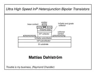
InGaAs (p++) B B C InP (n+) InGaAs (n-) InGaAsP (n+) Substrate InP (I.) Developed structure E InGaAs Cap layer 0.1 µm InP Emitter 0.1 µm InGaAs Base 0.1 µm InGaAs Collector 0.4 µm InGaAsP Cladding 0.7 µm InP Substrate Device defined to get an optimum light collection: 90% internal efficiency (8 µm long device ; lensed fibre)
Phototransistor-guide (HPT) - Triple mesa structure - Polymide bridge - Self-aligned base process Simple heterostructure Emitter contact Base contact Collecteur contact But: - device performance relies on the final cleaving process (couple of microns difference in cleaving decrease either the bandwidth (too long) or the efficiency (too short). - no possible integration with double heterostructure HBT
E C B Cleaving axis C B E Fabricated device Optical micrography SEM micrography Device size after cleaving 4x8 µm² DC currant gain : around 200 Device fabricated at IEMN
Introduction • Scholar study Optical modeling Alignment tolerance Optical structure optimization • 3T HPT making of Structure Characterization • HPT state of art • S parameters extraction • ft, fmax • equivalent model • Opto-microwave parameters • optical fc
HBT Load 50 W Cbc PIN photodiode Rbb Cc RD Lc Rc Rb 80 Cbe Re RL Iph CD Cpce Cpbe 70 Ree p-i-n/HBT Le 60 50 HPT Equivalent Input Noise (pA.(Hz)-½) 40 Iph Load 50 W External base cicuit Cbc HPT 30 Rbb 20 Rc Lc Cc Rb 10 Cbe RBE 0 Re RL 1 10 100 Cpce Cpbe Ree Frequency (GHz) Le Noise comparison HPT versus PIN + HBT Noise comparison HPT versus PIN + HBT - Equivalent input noise : • Advantage can be taken from HPT use
Opto-microwave properties Device size: 4x8 µm² Optical gain cut-off frequency > 45 GHz
Introduction • Scholar study Optical modeling Alignment tolerance Optical structure optimization • 3T HPT making of Structure Characterization • HPT state of art • 3T side illuminated HPT: • Trade off optimization (1.3 µm, 1.55 µm) • 8x4 µm² after cleaving • wInGaAs = 0.5 µm • wInGaAsP = 0.7 µm • DC gain: 200 • ft = 60 GHz • fcopt = 45 GHz
Introduction • Scholar study Optical modeling Alignment tolerance Optical structure optimization • 3T HPT making of Structure Characterization • HPT state of art • Electrical DHBT can go up several hundreds of GHz • BUT: • Optical HPT needs a sufficient absorbing layer • Side illumination requires a confinement layer • However 100 GHz operation has been reported
top side 2T side 3T Cut-off frequency state of art Dashed line consistent with emitter-base junction capacity limitation
Conclusion • Optimal light collection requires side illuminated structures • Side illuminated structures can be optimised • Up to 2x responsivity, 4x microwave power (6dB) • Best S/N results should be obtained with side illuminated structures • BUT: increased technological difficulties