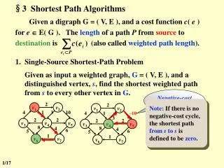
Download

1 / 16
160 likes | 303 Views
Interactive Shortest Path Part 3. A n Image Segmentation Technique. Jonathan-Lee Jones. Overview. Lattice Cut Introduction Method MRF Formulation Graph Construction Combining The Methods. Lattice Cut: Introduction. Method of over segmentation

E N D
Interactive Shortest Path Part 3 An Image Segmentation Technique Jonathan-Lee Jones
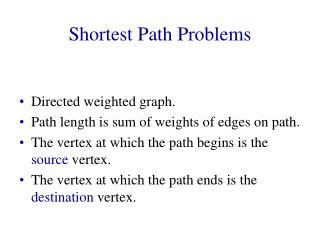
Overview • Lattice Cut • Introduction • Method • MRF Formulation • Graph Construction • Combining The Methods
Lattice Cut: Introduction • Method of over segmentation • Combines edge-based and region based methodologies • Fast:- Should increase performance as reducing the number of vertices in the graph.
Lattice Cut: Introduction Starting with a regular grid, and then alternate between improving the vertical boundaries between super- pixels (black lines in figure 1a-d) and the horizontal ones (red lines in figure 1a-d). At each step, they obtain a solution for all of the vertical (or horizontal) boundaries simultaneously.
Lattice Cut: Method • Assign label to each pixel, this corresponds to what vertical strip of superpixelsit belongs to. For example in figure 1a-d, superpixels 1-4 take label 0, superpixels 5-8 take label 1 and so on. • Then the solution for the unknown labels are formulated in terms of a Markov random field (MRF) model • The associated cost function contains both unary and pairwise terms.
Lattice Cut: Method • To create bands of labels as in figure 1e and maintain a regular lattice there are three additional constraints that must be obeyed by the label field. • Constraint 1: as we move from top to bottom along any column, the labels may only increment or decrement by a single value at a time (Figure 2a-y). • Constraint 2: as we move from left to right along any row, the labels must increase monotonically (Figure 2a-x). • Constraint 3: each vertical boundary must not cross each horizontal boundary more than once. Otherwise, we erroneously create extra superpixels and destroy the lattice structure (figure 2b-c).
Lattice Cut: MRF Formulation • Let P be a set of image pixels • xpbe a label assigned to pixel p from a finite label set L • And x be the collections of all pixel/label assignments. • The data terms Dp represent the penalty for pixel phaving label xp and the regularization terms Vpq, defined on a neighborhood system N , encourage spatial smoothness.
Lattice Cut: MRF Formulation Dpis the Unary cost associated with labelling the pixel p for any given label. Pairwise costs, calculated from a canny edge detector. Each gives an estimate of the strength Bp ∈ [0, 1] of a boundary at each pixel p. The pairwise cost between neighboring pixels p and q is set to C(1 − 0.5Bp − 0.5Bq) so the pairwise cost C is reduced when there is local evidence for a boundary.
Lattice Cut: Graph Construction Example graph construction with two pixels p and q, each of which can take label l ∈ {0, 1, 2}. Unary costs are associated with vertical links. Dpk is the unary cost for assigning the k’th label to pixel p. Pairwise costs are represented on horizontal links. Vmnis the pairwise cost assigning the m’th label to pixel p and the pq n’th label to pixel q. The labeling is determined by which vertical links are cut.
Lattice Cut: Graph Construction • Constraint Links • These are added to ensure that the 3 constraints of the method are conformed to. • Horizontal constraint links are added with infinity capacity between nodes {x,y,l} and {x+1,y,l} to ensure labels increase monotonically from left to right. • Diagonal Constraint links with infinite capacity are added between {x,y,l} and {x,y−1,l−1},{x,y+1,l−1},{x− 1, y, l−1} and {x+1, y, l−1} prevent non-sequential labels at neighboring pixels • Extra diagonal links can also be added to other pixels in a radius to set the minimum superpixel size to that radius.
Lattice Cut: Graph Construction Imposing sequential constraints a) Diagonal constraint links with infinite cost prevent non-sequential labels (constraint 1). b) To label the pixels 2,0 as in figure 3f we must now also cut one of these diagonal links: the cost for this solution becomes infinite and it will never be chosen. c) To additionally force the label map to sequentially increase (constraint 2) we replace the relevant pairwise terms and with constraint links of infinite cost. This gives labelingslike that in figure 3f an infinite cost.
Lattice Cut: Graph Construction This is minimised by using a subset K of the label set. This means that for any given pixel, the label can only be assigned within a localised value. Remember that sequential change in label across image is one of the constraints.
Lattice Cut: Graph Construction where W represents the interaction terms that restrict the set of feasible solutions on the graph over a set of labels L with neighborhood system M.
Combining The Methods • Use of a lattice like pre-segmentation to improve speed. • Cutting down number of nodes in graph to vertices only • Dynamically altering the resolution of the superpixels • Re-segmenting certain superpixels • Increasing the resolution of the superpixels until each user point is a within a pre-set distance from the boundaries of at least one superpixel • Foreground/background selection • Done for entire superpixels so should also speed up this step, and further cut down on the numbers of nodes looked at. • Grid Manipulation • Can the nature of the grid be changed to better suit our needs? • Can this stage be altered to include a prior?