Download
1 / 54
600 likes | 982 Views
Chapter 12 Secondary-Storage Structure. 12.1 Overview of Mass Storage Structure 12.2 Disk Structure 12.3 Disk Attachment 12.4 Disk Scheduling 12.5 Disk Management 12.6 Swap-Space Management 12.7 RAID Structure Disk Attachment 12.8 Stable-Storage Implementation

E N D
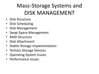
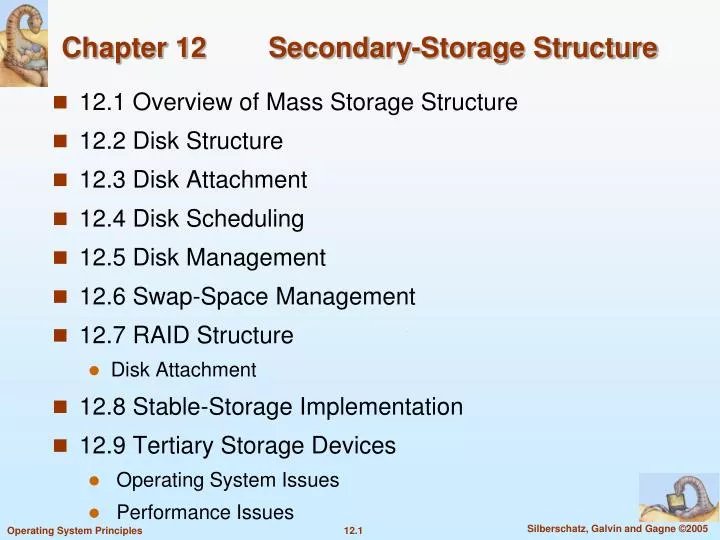
Chapter 12 Secondary-Storage Structure • 12.1 Overview of Mass Storage Structure • 12.2 Disk Structure • 12.3 Disk Attachment • 12.4 Disk Scheduling • 12.5 Disk Management • 12.6 Swap-Space Management • 12.7 RAID Structure • Disk Attachment • 12.8 Stable-Storage Implementation • 12.9 Tertiary Storage Devices • Operating System Issues • Performance Issues
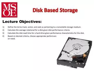
Objectives • Describe the physical structure of secondary and tertiary storage devices and the resulting effects on the uses of the devices • http://www.tomshardware.tw/review,2/ • http://www.zdnet.com.tw/enterprise/column/phoenix/ • Explain the performance characteristics of mass-storage devices • Discuss operating-system services provided for mass storage, including RAID and HSM (hierarchical storage management)
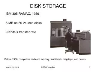
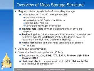
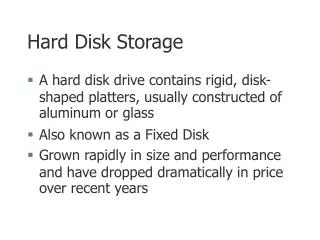
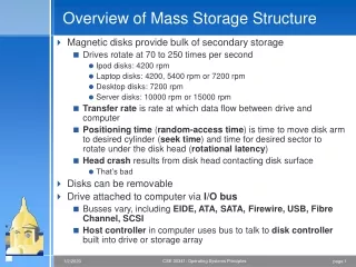
12.1 Overview of Mass Storage Structure • Magnetic disks provide bulk of secondary storage of modern computers • Drives rotate at 60 to 200 times per second (3600 to 12000 rpm) • Transfer rate is rate at which data flow between drive and computer (400Mb-6Gb/sec) • Positioning time (random-access time) is time to move disk arm to desired cylinder (seektime, 4 micro seconds) and time for desired sector to rotate under the disk head (rotational latency, 3 micro seconds) • Example: Hitachi Ultrastar C10K300 (http://www.zdnet.com.tw/news/hardware/0,2000085676,20137089,00.htm) • Head crash results from disk head making contact with the disk surface • Normally cannot be repaired
Overview • Disks can be removable • Held in plastic case • Drive attached to computer via I/O bus • Buses vary, including EIDE, ATA (Advanced Technology Attachment), SATA (Serial ATA), USB, FC (Fiber Channel), SCSI (Small Computer-System Interface) • Host controller in computer uses bus to talk to disk controller built into drive or storage array using memory-mapped I/O ports • Disk controllers usually have built-in cache (MB)
Magnetic tape • Was early secondary-storage medium • Relatively permanent and holds large quantities of data • Access time slow • Random access ~1000 times slower than disk • Mainly used for backup, storage of infrequently-used data, transfer medium between systems • Kept in spool and wound or rewound past read-write head • Once data under head, transfer rates comparable to disk • 20-200GB typical storage • Common technologies are 4mm, 8mm, 19mm, ¼ inch, ½ inch, LTO-2 (Linear Tape-Open) and SDLT (Super Digital Linear Tape) • 最新 LTO-5 (1.5 TB) http://www.zdnet.com.tw/enterprise/column/phoenix/0,2003032776,20145004,00.htm
12.2 Disk Structure • Disk drives are addressed as large 1-dimensional arrays of logical blocks, where the logical block is the smallest unit of transfer • A logical block is usually of size 512 bytes • The 1-dimensional array of logical blocks is mapped into the sectors of the disk sequentially. • Sector 0 is the first sector of the first track on the outermost cylinder • Mapping proceeds in order through that track, then the rest of the tracks in that cylinder, and then through the rest of the cylinders from outermost to innermost
In practice, it is difficult to convert a logical block number into cylinder, track, sector : defective sectors and the number of sectors per track is not a constant • CD-ROM and DVD-ROM increase their rotation speed as the head moves from the outer to inner tracks to keep the same data rate (the density of bits per track is constant, constant linear velocity, CLV) • In some disks, the rotation speed is constant, and the density of bits decreases from inner tracks to outer tracks to keep the data rate constant (constant angular velocity, CAV)
12.3 Disk Attachment • Host-attached storageaccessed through I/O ports talking to I/O busses • IDE, ATA, SATA, SCSI, FC • SCSI itself is a bus, up to 16 devices on one cable, SCSI initiator requests operation and SCSI targets perform tasks • Each target can have up to 8 logical units (disks attached to device controller • FC is high-speed serial architecture • Can be switched fabric with 24-bit address space – the basis of storage area networks (SANs) in which many hosts attach to many storage units • Can be arbitrated loop (FC-AL) of 126 devices
Network-Attached Storage (NAS) • NAS is storage made available over a network rather than over a local connection (such as a bus) • NFS (Unix) and CIFS (Windows) are common protocols • Implemented via remote procedure calls (RPCs) between host and storage • New ISCSI protocol uses IP network to carry the SCSI protocol so that hosts could treat NAS as directly attached
Storage Area Network (SAN) • Common in large storage environments • becoming more common • Multiple hosts attached to multiple storage arrays • flexible • FC is the most common SAN interconnect • InfiniBand is an emerging alternative SAN bus architecture (http://en.wikipedia.org/wiki/InfiniBand)
12.4 Disk Scheduling • The operating system is responsible for using hardware efficiently — for the disk drives, this means having a fast access time and disk bandwidth • Access timehas two major components • Seek timeis the time for the disk are to move the heads to the cylinder containing the desired sector. • Rotational latencyis the additional time waiting for the disk to rotate the desired sector to the disk head. • Minimize seek time • Seek time seek distance • Disk bandwidth is the total number of bytes transferred, divided by the total time between the first request for service and the completion of the last transfer
Disk I/O System Call • The system call for disk I/O specifies • This operation is input or output • The disk address for the transfer • Memory address for the transfer • The number of sectors to be transferred • For a multiprogramming system, normally, the disk request queue has several pending requests
Disk Scheduling • Several algorithms exist to schedule the servicing of disk I/O requests. • We illustrate them with a disk request queue of requests for blocks on cylinders (0-199): 98, 183, 37, 122, 14, 124, 65, 67 • The sequence indicates their order in time • Suppose the disk head pointer is initially at cylinder 53
First Come First Served (FCFS) The Illustration shows total head movement of 640 cylinders
Shortest Seek Time First (SSTF) • Selects the request with the minimum seek time from the current head position • SSTF scheduling is a form of SJF (shortest job first) scheduling; may cause starvation of some requests. • Illustration shows total head movement of 236 cylinders.
SCAN • The disk arm starts at one end of the disk, and moves toward the other end, servicing requests until it gets to the other end of the disk, where the head movement is reversed and servicing continues • Sometimes called the elevator algorithm • Illustration shows total head movement of 236 cylinders.
Circular SCAN (C-SCAN) • Provides a more uniform wait time than SCAN. • The head moves from one end of the disk to the other. servicing requests as it goes. When it reaches the other end, however, it immediately returns to the beginning of the disk, without servicing any requests on the return trip. • Treats the cylinders as a circular list that wraps around from the last cylinder to the first one.
Look and C-LOOK • Version of SCAN and C-SCAN • Arm only goes as far as the last request in each direction, then reverses direction immediately, without first going all the way to the end of the disk. LOOK or C-LOOK?
Selecting a Disk-Scheduling Algorithm • SSTF is common and has a natural appeal • SCAN and C-SCAN perform better for systems that place a heavy load on the disk • Performance depends on the number and types of requests • Requests for disk service can be influenced by the file-allocation method • The disk-scheduling algorithm should be written as a separate module of the operating system, allowing it to be replaced with a different algorithm if necessary • Either SSTF or LOOK is a reasonable choice for the default algorithm
Selecting a Disk-Scheduling Algorithm • Difficult to schedule for improved rotational latency • Disk manufacturers have implemented disk scheduling algorithms in the controller hardware • In practice, OS has other constraints • Demand paging may take priority over application I/O • Writes are more urgent than reads if cache is running out of free pages • Sometimes the order of writes must be kept to make the file system robust in case of system crashes
12.5 Disk Management • Low-level formatting, or physical formatting — Dividing a disk into sectors that the disk controller can read and write. • Header and trailer of sector contain information used by the disk controller, such as a sector number and an error-correcting code (ECC) • Most hard disks are low-level formatted at the factory • To use a disk to hold files, the operating system still needs to record its own data structures on the disk • Partition the disk into one or more groups of cylinders • Each partition is treated as a separate disk • Logical formatting or “creation of a file system” • Maps of free and allocated space and an empty directory
To increase efficiency, most file system group blocks together into clusters • Disk I/O is via blocks, but file I/O is via clusters • Some OS’s allow raw-disk • Example: DBMS • Boot block initializes system • The bootstrap is stored in ROM. • Only Bootstrap loader program is stored • A disk with a boot partition is called a boot diskor system disk
Booting from a Disk in Windows 2000 Master Boot Record (MBR)
Bad Blocks • Bad blocks are handled manually on simple disks, such as disks with IDE controllers • Example: chkdsk in MS-DOS • Sophisticated disk controller, like SCSI, maintains a list of bad blocks • Sector sparing: the controller could replace each bad sector logically with a spare sector • May invalidate optimization of disk-scheduling • Solution: provide spare sectors in each cylinder and a spare cylinder as well • Sector slipping: remaps all sectors from the defective one to the next available sector by moving them all down one spot
12.6 Swap-Space Management Swapping (Section 8.2) is to move least active process between main memory and disk Systems actually combine swapping with virtual memory techniques and swap pages, not entire processes Swap-space — Virtual memory uses disk space as an extension of main memory Its goal is to provide best throughput for the virtual memory system The amount of needed swap space depends on Amount of physical memory, amount of virtual memory, the way virtual memory is used It is safer to overestimate the amount of swap space required Linux suggest setting swap space to double the amount of physical memory
Swap-space can be carved out of the normal file system as a very large file: too inefficient • more commonly, it can be in a separate rawdisk partition. The goal is to optimize for speed rather than for storage efficiency • Swap-space management • In Solaris 1, swap space is used for pages of anonymous memory, which includes memory for the stack, heap, and uninitialized data of a process • Solaris 2 allocates swap space only when a page is forced out of physical memory, not when the virtual memory page is first created. • In Linux, swap space is also used for pages of anonymous memory or for regions of memory shared by several processes • Each swap area consists of a series of 4-KB page slots. Associated with each swap area is a swap map: an array of integer counters to indicate the number of mappings to the swapped page. Kernel uses swap maps to track swap-space use.
Data Structures for Swapping on Linux Systems The swapped page is mapped to three different processes This page slot is available
12.7 RAID Structure RAID -- Redundant Array of Inexpensive (or Independent) Disks multiple disk drives provides reliability via redundancy The mean time to failure (loss of data) of a mirrored volume depends on the mean time to failure of the two individual disks and the mean time to repair If the mean time to failure of a disk is 100,000 hours and the mean time to repair is 10 hours, then the mean time to loss of data of the mirrored disk system is 1000002/(2*10) = 500 * 106 hours Handling power failure: Write one copy first, then the next, so that one of the two copies is always consistent Add a NVRAM (nonvolatile RAM ) cache to the RAID array
Improvement in Performance via Parallelism • With disk mirroring, the number of reads per unit time has doubled • The transfer rate could be improved by striping data across the disks • bit-level data striping: splitting the bits of each byte across eight disks (or a multiple of 8 or a number divides 8) • block-level data striping: blocks of a file are striped across multiple disks. • With n disks, block i goes to disk (i mod n)+1 • Data striping has two main goals • Increase the throughput of multiple small accesses by load balancing • Reduce the response time of large accesses
RAID Levels Disk striping uses a group of disks as one storage unit. RAID schemes improve performance and improve the reliability of the storage system by storing redundant “parity” data Mirroring or shadowing keeps duplicate of each disk. Block interleaved parity uses much less redundancy. If the number of bits in the byte set to 1 is even (parity is 0) or odd (parity = 1) In the following figure, P indicates error-correcting bits, and C indicates a second copy of the data. In all cases, four disks’ worth of data are stored, and the extra disks are used to store redundant information for failure recovery
RAID Levels 1-3 Besides parity, Error Correcting stores two or more extra bits to reconstruct the data if a single bit is damaged. RAID 2 is not used. A single parity bit can be used for error correction as well as for detection. Normally RAID 3 includes a dedicated parity hardware and NVRAM cache.
read-modify-write cycle: a write requires four disk accesses: two to read and two to write. Skip the last paragraph about WAFL in p527. RAID Levels 4-6 Spreading data and parity among all disks to avoid the overuse of a single parity disk in RAID 4. RAID 5 is the most common parity RAID system. Stores extra redundant data to guard against multiple disk failures.
RAID 0 + 1 and RAID 1 + 0 SKIP p528 第 2 段 – p532 RAID 0 for performance, RAID 1 for reliability. A set of disks are striped, and then the stripe is mirrored to another stripe. Disks are mirrored in pairs and the resulting mirror pairs are striped. If a single disk fails in RAID 0 +1, the entire stripe is inaccessible, leaving only the other stripe available. With a failure in RAID 1+0, the single disk in unavailable, but the rest of the disks are available.
12.8 Stable-Storage Implementation Write-ahead log scheme requires stable storage To implement stable storage: Replicate information on more than one nonvolatile storage media with independent failure modes. Update information in a controlled manner to ensure that we can recover the stable data after any failure during data transfer or recovery. A disk write results in three possible outcomes: Successful completion Partial failure: only some of the sectors were written with the new data, and the sector being written during failure may be corrupted Total failure: The failure occurred before the disk write started, so the previous data remain intact
To be able to recover from a disk writing failure, the system must maintain two physical blocks for each logical block. An output operation is executed as follows: • Write the data onto the first physical block • When the first write complete successfully, write the same data onto the second physical block • Declare the operation complete only after the second write completes successfully • Recovery process • If both blocks are the same with no error, then no action • If a block contains a detected error, then replace it with the value of the other block • If neither block contains a detectable error, but their contents differ, then replace the content of the first block with that of the second • Performance could be improved by using NVRAM cache
12.9 Tertiary Storage Devices Low cost is the defining characteristic of tertiary storage Generally, tertiary storage is built using removable media Common examples of removable media are floppy disks and CD-ROMs; other types, like MO (magneto-optic disk) and tapes, are available
Removable Disks Floppy disk — thin flexible disk coated with magnetic material, enclosed in a protective plastic case Most floppies hold about 1 MB; similar technology is used for removable disks that hold more than 1 GB Removable magnetic disks can be nearly as fast as hard disks, but they are at a greater risk of damage from exposure Optical disks do not use magnetism; they employ special materials that are altered by laser light to have relative dark or bright spots The phase-change disk drive uses laser light at three different powers Low to read data Medium to erase the disk by melting and refreezing the recording medium into a crystalline state High to melt the medium into the amorphous state to write the disk
Removable Disks A magneto-optic disk records data on a rigid platter coated with magnetic material. Laser heat is used to amplify a large, weak magnetic field to record a bit. Laser light is also used to read data (Kerr effect) The polarization of the laser beam is rotated clockwise or counterclockwise depending on the orientation of the magnetic field. The magneto-optic head flies much farther from the disk surface than a magnetic disk head, and the magnetic material is covered with a protective layer of plastic or glass; resistant to head crashes
Read-write disks: The data on these disks can be modified over and over WORM (“Write Once, Read Many Times”) disks can be written only once. Thin aluminum film sandwiched between two glass or plastic platters To write a bit, the drive uses a laser light to burn a small hole through the aluminum; information can be destroyed but not altered Very durable and reliable Read Only disks, such ad CD-ROM and DVD, com from the factory with the data pre-recorded by pressing, instead of burning Removable Disks
Tapes Compared to a disk, a tape is less expensive and holds more data, but random access is much slower Tape is an economical medium for purposes that do not require fast random access, e.g., backup copies of disk data, holding huge volumes of data Large tape installations typically use robotic tape changers that move tapes between tape drives and storage slots in a tape library stacker – library that holds a few tapes silo – library that holds thousands of tapes A disk-resident file can be archived to tape for low cost storage; the computer can stage it back into disk storage for active use. A robotic tape library is called a near-line storage SKIP 12.9.1.3
Operating System Issues Major OS jobs are to manage physical devices and to present a virtual machine abstraction to applications For hard disks, the OS provides two abstraction: Raw device– an array of data blocks File system– the OS queues and schedules the interleaved requests from several applications How about removable storages?
Application Interface Most OSs handle removable disks almost exactly like fixed disks A new cartridge is formatted and an empty file system is generated on the disk Tapes are presented as a raw storage medium. An application does not open a file on the tape, it opens the whole tape drive as a raw device Usually the tape drive is reserved for the exclusive use of that application until the application exits or closes the tape device Since the OS does not provide file system services, the application must decide how to use the array of blocks Since every application makes up its own rules for how to organize a tape, a tape full of data can generally only be used by the program that created it
Tape Drives The basic operations for a tape drive differ from those of a disk drive locate positions the tape to a specific logical block, not an entire track (corresponds to seek) The read position operation returns the logical block number where the tape head is The space operation enables relative motion Most tape drives have a variable block size, which is determined when the block is written. If an area of defective tape is encountered during writing, that area is skipped and the block is written again Tape drives are “append-only” devices; updating a block in the middle of the tape also effectively erases everything beyond that block An EOT mark is placed after a block that is written
File Naming The issue of naming files on removable media is especially difficult when we want to write data on a removable cartridge on one computer, and then use the cartridge in another computer Contemporary OSs generally leave the name space problem unsolved for removable media, and depend on applications and users to figure out how to access and interpret the data. Some kinds of removable media (e.g., CDs and DVDs) are so well standardized that all computers use them the same way
Hierarchical Storage Management (HSM) A hierarchical storage system extends the storage hierarchy beyond primary memory and secondary storage to incorporate tertiary storage — usually implemented as a jukebox of tapes or removable disks Usually incorporate tertiary storage by extending the file system Small and frequently used files remain on disk. Large, old, inactive files are archived to the jukebox. HSM is usually found in supercomputing centers and other large installations that have enormous volumes of data
Speed Two aspects of speed in tertiary storage are bandwidth and latency Bandwidth is measured in bytes per second Sustained bandwidth– average data rate during a large transfer; # of bytes/transfer time Data rate when the data stream is actually flowing Effective bandwidth– average over the entire I/O time, including seek or locate, and cartridge switching Drive’s overall data rate Performance Issues: Speed, Reliability, Cost
Access latency – amount of time needed to locate data. Access time for a disk – move the arm to the selected cylinder and wait for the rotational latency; < 5 milliseconds Access on tape requires winding the tape reels until the selected block reaches the tape head; tens or hundreds of seconds Generally say that random access within a tape cartridge is about a thousand times slower than random access on disk If a jukebox is involved, the access latency is much higher The low cost of tertiary storage is a result of having many cheap cartridges share a few expensive drives A removable library is best devoted to the storage of infrequently used data, because the library can only satisfy a relatively small number of I/O requests per hour
Reliability A fixed disk drive is likely to be more reliable than a removable disk or tape drive An optical cartridge is likely to be more reliable than a magnetic disk or tape A head crash in a fixed hard disk generally destroys the data, whereas the failure of a tape drive or optical disk drive often leaves the data cartridge unharmed