Download
1 / 30
320 likes | 507 Views
Cerenkov Free Electron Laser ( CFEL ) And Hybrid FEL Devices. (asgekar@physics.unipune.ernet.in). Vivek B. Asgekar Physics Department University of Pune Pune 411 007, INDIA. Undulator Field Profile. -- Free Electron Laser (FEL). - idea was proposed in 1972

E N D
Cerenkov Free Electron Laser ( CFEL ) And Hybrid FEL Devices (asgekar@physics.unipune.ernet.in) Vivek B. Asgekar Physics Department University of Pune Pune 411 007, INDIA
-- Free Electron Laser (FEL) • - idea was proposed in 1972 • first experiment 1977-78 • * • * • * : Halbach PM Undulator • * :different Undulator configurations • * : new devices ( 1983 Cerenkov FEL) • * • *
-- Free Electron Laser basic idea to produce electron bunches < radiation wavelength
Free Electron Laser schematic e bunch COUPLING DEVICE + em radiation UFEL COUPLING DEVICE ---- UNDULATOR SLOW WAVE STRUCTURE(Cerenkov effect) CFEL (metal grating) S P FEL
-- BUNCHING Interaction of e beam with radiation field (~ a few mm) (~ a few microns) Energy modulation on scale length of wavelength + Dispersive action of the coupling device Energy modulation space modulation (Bunches)
Undulator Free Electron Laser (UFEL) -- Electron beam , temporal structure -- -- Undulator ---- ----
-- electron trajectory ……… for the sinusoidal trajectory -- amplitude -- undulator induces a transverse component of velocity
SYNCHRONIZATION -- electrons from the and the second bunch subsequent bunches em radiation field + undulator field -- beating of rad. field & und. field gives
-- Cerenkov Free Electron Laser ( CFEL) Cerenkov condition dielectric film conductor Fundamentals of Microwave Engineering -- R.E.Collins
-- Synchronization Beam velocity = phase velocity of the mode for mode
Advantages : 1) Low energy accelerator i) pulse modulators [ 50 – 250 keV] Make the device compact ii) Marx Generators [ 500 keV – 1 Mev] iii) rf accelerators [ up to ~ 5MeV] + 2) Short interaction region ( ~ 10 to 30 cm) II -------------------------- A Table Top Device Dispersion : Free Space Limitations : i) wavelength range limited by beam size ii) power limited by dielectric breakdown
1) single slab configuration Different Dispersion Relations for Different Configurations 2) double slab configuration 3) cylindrical slab configuration Dielectric loaded film waveguide (100 micron CFEL at Frascati)NIM A272,1988,132
NIM A259,1987,125 -- double slab geometry -- dielectric constant : 2.12 ( TPX ) film thickness – 48 microns film thickness – 92.5 microns
- X-band Cerenkov FEM amplifier Parameters of the expt : electron energy : 890 keV beam current : 500 Amp pulse duration : 100 nsec interaction region : 17.8 cm dielectric constant : 10 f = 9 GHz 100 kW 3 MW ( eff. ~ 3 %) PRL 65,2989,1990
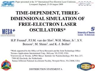
A MM-WAVE, TABLE-TOP CERENKOV FREE ELECTRON LASER* I. de la Fuente, P.J.M. van der Slot, K. J. Boller University of Twente, Laser Physics & Non-Linear Optics Group, PO Box 217, 7500 AE Enschede, The Netherlands [2004 FEL Conf] Nominal operational frequency 50 GHz Accelerating voltage From 65 to 100 kV Liner Material fused quartz Dielectric constant : 5.8 Thickness 1.3 mm Inner diameter 3 mm Length 250 mm Magnetic field on axis 0.15 T Beam diameter 2 mm Beam current 800 mA Table 1.1. characteristics of the CFEL
HybridFELDevices Self Amplified Spontaneous Emission ( SASE ) FEL --- [ 4 GLS ] -- a single pass device -- very large gain, noise/seed to saturation in one pass -- no mirrors required -- electron beams with low energy spread & high brightness -- electron motion in an Undulator even hormonic oscillations along the undulator axis and odd harmonic perpendicular to the axis
SASE - FEL Dattoli et. al. J Appl Phys 97 , 113102, 2005
SEGMENTED UNDULATOR SASE - FEL
Pierce parameter ; * growth rate * undulator length to reach saturation * power transfer at saturation * limit on beam energy spread
space -- Eqs of motion in space distribution function of particles in Substituting the expression for Expanding the integral in Fourier series and keeping the terms in synchronism with the radiation field
[ V.B.Asgekar & G.Dattoli Optics Communications 206 , p 373,2002 and 255 , p309, 2005]
T(z) ---- UFEL (10 micron ) Q3(z) ---- 3rd harmonic of UFEL (30 micron ) F2(z)+H2(z) ---- UFEL (30 micron) + UFEL (10 micron) F(z)+H(z) ---- CFEL (30 micron) + UFEL (10 micron )
F(z)+H(z) ---- CFEL (300 micron)+UFEL(100 micron) T(z) ---- UFEL(100 micron)
-- FEL Oscillators ( ?? ) ( gain > losses) -- integrate other types
THANKS TO : -- FZ Rossendorf (- Prof Dr Manfred Helm, - FEL Group) -- AvH Stiftung, Bonn