Download
1 / 42
431 likes | 660 Views
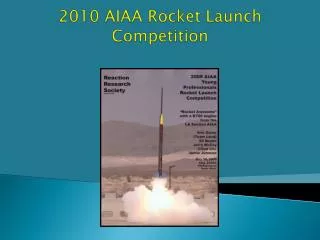
AIAA Design/Build/Fly Competition - 2011. University of California, Irvine – UCI Team Caddyshack. Introduction. The UCI AIAA student chapter participates in the annual AIAA Design Build Fly (DBF) competition.

E N D
AIAA Design/Build/Fly Competition - 2011 University of California, Irvine – UCI Team Caddyshack
Introduction • The UCI AIAA student chapter participates in the annual AIAA Design Build Fly (DBF) competition. • This competition gives the engineering students a chance to apply classroom knowledge, gain hands on skills, and experience an industry level project-development from conceptual design to building and testing an optimized final product. • Over the past 6 years this project has grown substantially in size and skill with the help of previous DBF students, currently working in the aerospace industry, who meeting with the current team weekly.
Outline • Introduction • Team Organization • 2011 Competition • Conceptual Design • Preliminary Design • Detailed Design • Manufacturing • Testing • Expected Final Performance
Team Overview • Aerodynamics: Computes flight characteristics and necessary wing dimensions. • Propulsion: Analyzes propulsion system to find best motor, propeller and battery combination. • Structures: Optimizes load-bearing components and maintains a weights build-up of the aircraft. • Payload: Designs and manufactures steel payload and restraints for the payload and aircraft. • Stability & Control: Ensures aircraft meets S&C standards and works closely with aerodynamics to predict flight performance.
2011 Competition • Competition consists of 3 missions: • Mission 1: Complete as many laps as possible in a 4-minutes. time frame (M1 = Nlaps/Nmax) • Mission 2: 3 laps with a steel bar payload. (M2 = 3x(Payload weight/Flight weight)) • Mission 3: 3 laps with a team-selected quantity of golf balls. (M3 = 2x(Nballs/Nmax))
2011 Competition (Cont.) • Constraints for 2011: • Battery weight: ¾ lb • 20 amp slow-blow fuse • Aircraft must fit in a commercially-available carry-on suitcase. • L + W + H = 45inches (no dimension can exceed 22 in.) • Suitcase must include entire flight system, including aircraft, battery and all required parts and tools. • Golf balls are regulation sized and the steel bar payload dimensions are constrained: 3 in. width x 4 in. length minimum. • Aircraft must be hand-launched.
Conceptual Design • Sensitivity Analysis • Configuration Figures of Merit • Aircraft Configuration • Subsystems Selection • Motor Position • Landing Methods • Yaw Control • Wing Attachment Methods • Payload Configuration • Final Configuration
Sensitivity Analysis • The objective of this analysis is to identify the mission parameters that have the largest impact on the score. • A maximum of 64 golf balls and 9 laps were the benchmark values, determined using the data from past DBF competitions. • Thrust and drag models were used in a simulation program to design hundreds of planes and perform this analysis. • Mission 1 favors a small plane and payload with a large propulsion system. • Missions 2 and 3 favor a large plane with a high wing loading.
Configuration Figures of Merit • In order to select an aircraft configuration, a scoring system based on figures of merit was produced. Each was weighted based on results of the scoring analysis: • System weight (35%) • L/D (20%) • Cargo space (15%) • Maneuverability (10%) • Manufacturing (10%) • Hand launch (10%)
Aircraft Configuration Final Decision: Flying Wing Would be able to hold a maximum amount of cargo using the lifting surface as the payload bay without a significant drag penalty. Mono Plane- (Conventional) Relatively easiest to design and build. Known comparative values for performance. Relatively heavy configuration not optimized for specific competition. Flying Wing Efficient use of space. Lack of unnecessary elements decreases weight. High L/D Significantly less stable and more difficult to manufacture. Delta Wing Fly at high angle of attack. Allow additional cargo placed in wing. More unstable than a conventional and somewhat more complex to design and manufacture. Biplane Slightly more stable and higher structural strength. Much heavier and unnecessary additional elements.
Motor Position • Tractor- Lightweight, higher efficiency and less dangerous hand launch. • Pusher- greater lift due to lack of prop-wash, limits the maximum amount of sweep and a dangerous hand launch. • Double Tractor- Smaller propellers, increased cargo space in center, less dangerous hand launch, increased weight and difficulty in locating the CG. • Push-Pull- Increased weight, limits maximum sweep and provides a more dangerous hand launch.
Landing Methods • Belly Landing- Low weight, low drag, would be difficult to hand launch and vulnerable to fatigue. • Skid/ Handle- Improved hand launch, increased structural support, potential additional storage space and slight increase in weight and drag. • Skid & Wire- Decreased stopping distance, minor increase in weight and increase in drag. • Tricycle- Reliable and high strength, however significant increase in weight, drag and difficulty of hand launch.
Yaw Control • Winglets- Reduced drag, light weight and provides yaw stability. • Wingtip rudders- Increased pilot control and increased weight. • Aft Vertical tail-Greater moment to correct yaw and significant increase in weight. • Split Flaps- Provides only a minor increase in weight, complex and difficult to implement correctly and cause and increase in drag.
Payload Configuration • Fully enclosed internal payload compartment- Less drag and a lower weight. Requires a larger t/c airfoil or a larger aircraft. • Fuselage (BWB) style compartment- More efficient method of cargo placement near the Center of Gravity, increased drag and difficulty to manufacture.
Preliminary Design • Design and Optimization Programs • Design Methodology • Mission Model • Aerodynamics • Airfoil Selection • Wing Sizing • Propulsion Sizing • Drag • Lift • Stability and Control • Mean Aerodynamic Chord • Winglets
Programs Used During Design and Optimization • SolidWorks: used to model aircraft prototypes and to help determine airfoil selection • XFOIL: Used to analyze possible airfoil choices for aerodynamic characteristics • Microsoft Excel: Used extensively for data analysis, storage and graphing • AVL: Used for flight-dynamic analysis and to ensure overall stability of the aircraft • MATLAB: Used to create an optimization program
Design Methodology • The Aerodynamics team planned and organized the design process into several design steps outlined in the flowing diagram. • A conceptual design is produced using the sensitivity analysis results. • A preliminary design is developed using the conceptual design results and initial estimates. • An optimization program is developed in Matlab to model the performance of a design for all of the missions. • Several iterations of optimizing, building and testing are done to produce a high performance aircraft.
Mission Profile Optimization Program • The mission profile was modeled using for loops and while loops in MATLAB. • The aerodynamic and propulsion forces were computed for every loop-iteration to determine the change in position and velocity of the aircraft during that period of time. • The program assumed some initial conditions for takeoff such as hand launch velocity and wind conditions. • The mission model program computes: • the energy used • the number of laps completed in 4 minutes • The maximum payload capacity a design could carry. • The total flight score is computed for several designs which resulted in an optimized design.
Airfoil Selection • The majority of airfoils that were considered were the reflex type for our flying wing. • Studies were done using XFOIL and SolidWorks to determine which airfoil best suited our needs. Coefficient of moment vs. angle of attack NACA 4-digit symmetric series study
Wing Sizing • The figure to the right shows a plot of the total drag as a function of the aspect ratio for mission three during takeoff. • Wing loading was optimized based on the total flight score using our mission profile MATLAB program.
Propulsion • Propeller Selection • Pitch-High pitch performs better at high speeds while low pitch performs better at low speeds. • Diameter- Larger diameter= more thrust and more power required from motor. • Mission 1: High pitch small diameter. • Missions 2 & 3: Lower pitch and larger diameter. Battery Selection • Considered several different battery types and the capacity-to-weight ratios. • A mission profile was used to determine an estimate of the amount of energy needed to complete each of the missions. • Motor Selection • Based on the battery and the current limitation of 20A, the maximum power the battery could supply to the motor is 300 W.
Drag • The drag was computed using the equivalent flat plate area method.
Lift • The wing was optimized for the cruise of mission two and three. • Washout helped focus the peak of the CL distribution.
Stability and Control • We calculated our MAC and simulated our aircraft’s geometry through AVL • The figure to the right shows the resulting pole-zero map of the eigenvalues calculated by the program.
Stability and Control WINGLETS An eignemode analysis made in AVL showed that the flying wing was susceptible to low Dutch roll damping. Dutch roll was clearly visible during test flights, but Pilot still maintained good control. Sized for Dutch roll damping above 0.02. Optimized Winglet Dimensions Height c/4: 9.5 in Sweep: 37 degrees Distance behind LE: 6.0 in Taper ratio: 0.7
Wing Spar Design • We modeled the wing spar as an I-beam. • Carbon strips were laid on the top and bottom of the wing with a 5/8” diameter carbon rod running between the strips to create our spar. • Testing later on showed that the wing with two spars was favored over the single spar.
Central Structure Design • In an effort to reduce weight, the motor mount, landing skids and launch handle were combined into one carbon fiber structure that was integrated into the center wing section. • This design proved to be very efficient in cargo space utilization. • The forward end is used as an electronics compartment to house the speed controller and the fuse. • The skid and handle section was designed as a channel that was sized to fit the propulsion battery pack.
Manufacturing • We used molding methods investigated over summer to create our center section. • A male and female mold were created using SolidWorks template printouts and hotwire cut foam.
Manufacturing • Foam wings were created and hollowed out using wooden templates and a hotwire as investigated over summer. • Wings were then coated with fiber glass and a strip of carbon fiber for strength.
Testing • Wingtip Testing • Propulsion Testing • Handle Design Tests • Flight Tests
Wingtip Testing • Wing tip testing was used to confirm and validate wing-spar calculations and our hollow core foam design. • Testing was performed by securing the tips of a wing and loading it mid-span until failure occurred.
Propulsion Testing • Static thrust testing was conducted to measure the performance of various propulsion systems. • Dynamic thrust testing was conducted using a load cell that was mounted to a custom-designed sliding motor mount and was used to collect dynamic thrust data during flight. • This data was used to accurately model the dynamic thrust in the mission profile optimization program. • Fuse and battery testing were also conducted in the lab to determine the limits and range of operation.
Handle Design Tests • Different handle designs were created and tested initially to find which best suited the hand launcher to give him control and stability at take off.
Test Flight Results The following are a combination of both prototypes, and were used to calibrate the preliminary design. Takeoff speed: 30 ft/s Max wing loading: 28 oz Locating CG for stable flight: 15% static margin Dutch roll damping: Controllable Lap time: 37 s Prototype I Prototype II
Test Flight Results • Prototype I • Provided insight into launch and landing techniques. • Provided data for the calibration of the wing loading. • Prototype II • Improved stability. • Increased payload space.
Competition Results • Maximum of 4 flight attempts allowed • Mission One: • 1st flight attempt: 6 laps in 4 minutes • Late in the day • Mission Two: • 2nd flight attempt: fuse blew within seconds after hand launch • Noon, +90°F, No wind • 3rd flight attempt: ran out of battery with one more turn left in the course • Late in the day • Very spectacular flight • 4th flight attempt: Propulsion strategy gone amiss • Noon, • Even with a reduced payload, our plan to increase thrust on the downwind blew the fuse.
Lessons Learned • The conditions surrounding the fuse in Tucson are very different than those in Irvine. The fuse will blow at a lower current in Tucson. • Flying later in the day helped with the above handicap, when it was cooler. In fact, heavy planes like those from Israel and MIT skipped their noon rotation and waited till the late afternoon to fly their airplanes (9 lbs!!). • Conduct propulsion tests and test flights with competition weather conditions in mind.