Download
1 / 32
320 likes | 460 Views
Transverse Damper in 2012. presented by W. Hofle. Special acknowledgements: H. Bartosik , V. Lebedev , D. Valuch , V. Zhabitsky BE-OP, BE-RF. Transverse Damper in 2012. where do we stand end of 2011 plans for 2012 – new features performance with 25 and 50 ns

E N D
Transverse Damper in 2012 presented by W. Hofle Special acknowledgements: H. Bartosik, V. Lebedev, D. Valuch, V. Zhabitsky BE-OP, BE-RF W. Hofle @Chamonix
Transverse Damper in 2012 • where do we stand end of 2011 • plans for 2012 – new features • performance with 25 and 50 ns • what changes with increased energy • running at higher gains in ramp • noise: a feedback view • tune measurement: feasibility and plans W. Hofle @Chamonix
Where do we stand end of 2011 • procedures for setting-up well established & highly automized • running with feedback on @50 ns spacings at all times • tests with 25 ns spacing show criticality of set-up of delay • abort gap cleaning and injection cleaning fully operational • fine setting-up of feedback phase done, in line with expectations, but will re-visit in 2012 • contribution to noise from cabling identified, correction. i.e. re-cabling of pick-ups for one system (H.B2) done this stop. • batch selective excitation demonstrated • see Evian talk by D. Valuch • also re-commissioning • in 2012 see D. Valuch @Evian W. Hofle @Chamonix
ADT through the cycle W. Hofle @Chamonix
Gated excitation gate, 11 ms (example) • white noise generated on FPGA running at 40 MS/s • after VME upgrade available for all dampers • tested on all dampers of beam 2 (H and V plane) • noise can be filtered by IIR lowpass filter D. Valuch, M. Jaussi, D. Jacquet, T. Levens W. Hofle @Chamonix
Selective blow-up (2 pilots) hardware / firmware ready for aperture tests and quench tests 2 mm 18 mm stops at 18 mm aperture W. Hofle @Chamonix
Comparison loss maps damper (ADT blow-up) loss map 3rd order resonance S. Redaelli, R. Schmidt, D. Valuch, D. Wollmann, M. Zerlauthet al. W. Hofle @Chamonix
Plans for 2012 – new features (1) • user interface for loss maps (purely software effort), “expert” interface later sequencer (?) • observation of two selectable bunches in a continuous way for tune measurement with data streamed to software in packages of 4096 turns, tests for software interface pending • for tune measurement: gain modulation within a turn to have lower gain for a witness bunches train (leading 12 bunches) • “dead-band” / “dead-band” with commutation of FB sign later to be considered (“dead-band” do not damp oscillation before it reaches x mm, x adjustable) • tune measurement from witness bunch train (ADT data or BBQ) W. Hofle @Chamonix
Plans for 2012 – new features (2) • bunch mask based observation (more than 8 bunches) permitting online injection quality checks along batch (current observation limited to 8 bunches) • automatic setting of bunch intensity dependent gain, permitting observation of pilot bunches at injection: still some procedure to protect equipment to be defined • post mortem data display for ADT to be commissioned W. Hofle @Chamonix
Performance with 25 ns and 50 ns spacing • 50 ns: 10 MHz bandwidth required and available • 25 ns: 20 MHz bandwidth required more difficult set-up • for 25 ns frequency response improvements under study (also important for abort gap cleaning): cable dispersion, and entire amplifier change under scrutiny kick @ 10 MHz, 10% left measured on power amplifier (blue curve on kicker, green on anode of tetrode) LHC-PROJECT-REPORT-1148 W. Hofle @Chamonix
50 ns spacing 40 turns, 1/40 = 0.025 1.2x10¹¹ per bunch 50 ns spacing well under control with damper instability calculation by N. Mounet W. Hofle @Chamonix
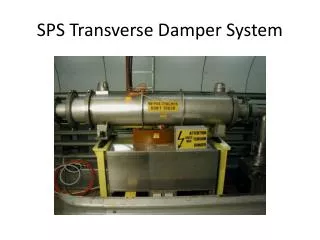
Transverse damper adjustments Tbeam • Key elements: • beam position monitor(s) • signal processing system • power amplifiers • kickers (electric field) Tsignal • Key parameters: • Feedback loop gain • phase and • delay W. Hofle @Chamonix
1st test with 48 bunches @25 ns spacing (1) damper off, vertical plane damper on, vertical plane data from post mortem offline-analysis 26th August 2011: two injection attempts at Q’=2, one with damper on, one with damper off; subsequent MDs with 25 ns done with high Q’ (e-cloud instability) see MD note under approval, H. Bartosik, W.Hofle W. Hofle @Chamonix
1st test with 48 bunches @25 ns spacing (2) damper off, vertical plane damper on, vertical plane damper off: frequencies of instabilities < 2.5 MHz damper on: frequencies above 14 MHz unstable: but delay was not yet correct MD note under approval, H. Bartosik, W.Hofle W. Hofle @Chamonix
What changes with increased energy ? • impedance higher with collimators closer to beam • physical beam size smaller, impact of noise higher • marginal changes for 4 TeV, not an issue • 7 TeV reduction of noise advised (keep performance) • 7 TeV, higher electronic gain required due to stiffer beam means saturation, we run out of steam, re-shuffling of gain with some low power amplifiers needing re-design (for LS1) W. Hofle @Chamonix
Running at higher gains in ramp • maximum gain given by stability limits of feedback + beam • impact of noise other than from damper pick-ups on emittanceincrease is reduced at high gain • no dependence on gain of impact of damper pick-up noise on emittance • higher gain and higher pick-up noise makes tune signal seen by BBQ noisier, i.e. noise floor outside tune rises • this is an undesired effect for the measurement of the tune • MDs planned for 2012 W. Hofle @Chamonix
How we ran in 2011 with 50 ns beam damper gain hor beam 1 (linear scale) HIGH @450 GeV before prepare for ramp increase of damper (electronic) gain in ramp To maintain approx. same damping rate ramp (energy) drop of damper gain increased BBQ amplitude = more residual beam oscillations => potentially leading to blow-up; but signal needed for tune feedback which is switched on here BBQ hor Beam 1 amplitude prepare for ramp ramp Injection plateau W. Hofle @Chamonix
Gain limit from stability faster than 10 turns damping range of operation contour lines at n/80 turns n=1…8 and 0.002 (1/t) design (40 turns damping) gain is the fraction of detected oscillation that is corrected in a single turn V. Zhabitsky et al. W. Hofle @Chamonix
Damping : variation with tune range of operation report in preparation, looked at 8 pick-ups, injection and collision some small optimizations possible, like in plot above consider beam-beam tune shift for future (pi-mode !) W. Hofle @Chamonix
Damping time : variation with gain measurements versus expectation vertical, beam 2 @3.5 TeV W. Hofle @Chamonix
Tune from residual damper signal PU signals with noise simulated measured (2 PU signals) beam motion below damper detection level i.e. not visible for damper V. Lebedev, W. Hofle, D. Valuch et al. IPAC 2011 W. Hofle @Chamonix
Closed loop transfer function N(s)Y(s) • beam system input system output G(s) perturbation PU F(s) visible to damper • feedback • open loop • output of closed loop • closed loop transfer function W. Hofle @Chamonix
Tune Measurement: feasibility and plans abs. value of pick-up signal simulated damping of 1 mm error, and simulated noise floor matching observed fluctuation on PU signals (2 mm rms, 5 mm peak) W. Hofle @Chamonix
Tune Measurement: feasibility and plans kick signal PU signal actual beam (not visible by FB) numerical simulation with correctly adjusted feedback phase 8000 turn FFT relatively noisy W. Hofle @Chamonix
Tune Measurement: feasibility and plans tune (nominal 0.32, collision V-plane) kick signal PU signal actual beam (not visible by FB) numerical simulation with correctly adjusted feedback phase average of eight 1000-turn FFT from a set of 8000 turns, one bunch, minimum of PU signal gives tune W. Hofle @Chamonix
Tune Measurement: feasibility and plans tune (shifted by reactive part of FB) kick signal PU signal actual beam (not visible by FB) numerical simulation with badly adjusted feedback phase (30o off) average of eight 1000-turn FFT from a set of 8000 turns, one bunch, minimum of PU signal gives un-shifted tune ! W. Hofle @Chamonix
Summary tune measurement • lower ADT gain for first bunch train of 12 bunches • implement in ADT observation of two selectable bunches • observe results of lower gain, incl. on BBQ (gated BBQ ?) • check practical feasibility of tune from residual damper signal • implement final solution in LS1 W. Hofle @Chamonix
Summary • a number of new features under development • 50 ns well under control • 25 ns requires attention for setting-up • improvements for lower noise under way • improvements for frequency response under way • compatibility with tune measurement system • to be tackled with witness bunches for 2012 run W. Hofle @Chamonix
Spare slides W. Hofle @Chamonix
Beam Position module (Bpos) Calculates normalized beam position bunch by bunch, independent of intensity many different sources contribute to noise 16 bit ADCs W. Hofle @Chamonix
Beam Position module (Bpos) Normalized bunch position calculation angle fDS determined during setting-up, different settings required for different gains in pre-amplification chain propagation of noise from 4 ADCs to final beam position measurement W. Hofle @Chamonix
Plans for TS 2011 and 2012 run delta signal noise contribution from cable the first to eliminate last batch no beam recabling of one system: • 7/8” coaxial cable damage during the initial installation. • Evaluation of a new type transmission line without of cable without corrugation. W. Hofle @Chamonix