Download
1 / 31
310 likes | 484 Views
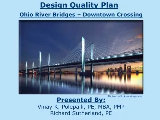
Ohio River Bridges East End Crossing. Ohio Transportation Engineering Conference, October 29, 2014. Rock Anchors for Permanent Cut Slope Support. Outline. 1 Project Background. 2 Geotechnical Explorations. 3 Analysis and Design. 4 Construction. 5 Lessons Learned.

E N D
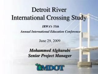
Ohio River Bridges East End Crossing Ohio Transportation Engineering Conference, October 29, 2014 Rock Anchors for Permanent Cut Slope Support
Outline 1Project Background 2Geotechnical Explorations 3Analysis and Design 4Construction 5Lessons Learned
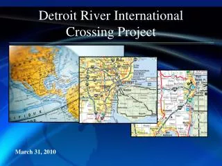
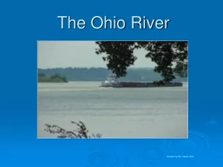
Ohio River Bridges East End Crossing • P3 to complete outer loop around Louisville/Southern Indiana • 2,510’ long, 3-span cable stay bridge over Ohio River • 8 miles of roadway • 1,680-foot long tunnel under historic property
Ohio River Bridges East End Crossing • Key Players • Indiana Finance Authority in conjunction with Indiana DOT and Kentucky Transportation Cabinet • WVB East End Partners (Walsh Investors, LLC, VINCI Concessions and Bilfinger Project Investments) • Walsh/Vinci Construction • Jacobs Engineering – Lead Designer • Stantec Consulting Services Inc. – Geotechnical Consultant, Sections 4 and 5
Geotechnical Explorations • 15+ different phases of geotechnical explorations, over 300 borings by various consultants/agencies • Conventional SPT/ST Borings • Rock Core Borings (vertical, horizontal and inclined) • Observation Wells/PZ’s/Packer Testing • Downhole Camera • Geophysical • Outcrop Mapping
South Portal Design Parameters North Portal Design Parameters
Groundwater Conditions – South Portal • Hydrogeology – karst dominated • GW typically found within bedrock joints/fractures in Louisville Limestone • GW levels vary from Soil/Bedrock interface to 30 feet below interface • Design Flow – 0.075 gpm/sq. ftof wall
Technical Procedure for Top Down Construction Walls • Indiana DOT Standard Specification 734 – Permanent Earth Retention System for Cut-Wall Application, 2012. • FHWA0-IF-03-017 Geotechnical Engineering Circular No. 7, Soil Nail Walls, March 2003. • FHWA-IF-99-015 Geotechnical Engineering Circular No. 4, Ground Anchors and Anchored Systems, June 1999. • AASHTO LRFD Bridge Design Specifications.
Top Down Wall Design - Rock Anchor Service Life • Technical Procedure Requires 75 Year Service Life. • National Cooperative Highway Research Program, Report 477, Recommended Practice for Evaluation of Metal Tensioned Systems in Geotechnical Applications, 2002. • Design for Factor of Safety = 2 after 75 years by providing extra capacity based on rock resistivity.
Top Down Wall Design - Rock Anchor Service Life Service Life, in years = (ro – rcri) / Crate + Sc ro = actual rock anchor radius provided. rcri = rock anchor design load critical radius. Crate = corrosion rate per year from Nomogram. Sc = service life contribution for rock anchors from surface corrosion protection coating; Sc = 20 years maximum.
Construction Photo Date 5/29/14. Wall R10 construction progress to shale level.
Construction Photo Date 5/17/14. Wall R12 construction progress to shale level.
Construction Photo Date 7/22/14. Wall R17 construction progress to bench level.
Construction Photo Date 11/6/13. Wall R10 rock replacement pre pour.
Anchor Testing Requirements • Post Tensioning Institute, Recommendations for Pre-stressed Rock and Soil Anchors. • Failure Tests – 1 in Limestone, 1 in Shale – On additional anchors. • Performance Tests – 1 test per 50 production bolts – On additional anchors. • Proof Tests – 20% of anchors, 100% of anchors installed by jackleg - On production anchors. • Lock Off at Design Load – All production anchors.
Construction Photo Date 11/7/13. Wall R12 rock bolt performance testing.
Lessons Learned - Rock Anchor Walls • Consider the rock anchor service life issue early in the design phase. Conceptually this issue is time consuming, but can provide significant savings. • Consider the issue of dosage rates for steel fibers in shotcrete and also the “Buy America Act” requirements early in the design phase. Dosage rates should be high enough to offset other issues that may occur during shotcreting. • Consider whether adhesion will occur between the shotcrete and rock, and how this affects required shotcrete thickness. • Consider a strategy for rock replacement early in design phase. If required, it should not slow down the construction phase. • Select locations for drain strips that will not interfere with rock bolt locations or blasting for penetrations. • Poorer quality rock will consume more man hours and shotcrete volume than higher quality rock. • Some rock anchors do not pass inspection. Order extra rock anchors.