Download
1 / 28
280 likes | 408 Views
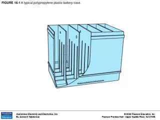
FIGURE 15-1 Photo of a cutaway battery showing the connection of the cells to each other through the partition. FIGURE 15-2 Chemical reaction for a lead–acid battery that is fully charged being discharged by the attached electrical load.

E N D
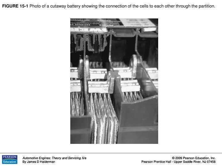
FIGURE 15-1 Photo of a cutaway battery showing the connection of the cells to each other through the partition.
FIGURE 15-2 Chemical reaction for a lead–acid battery that is fully charged being discharged by the attached electrical load.
FIGURE 15-3 Chemical reaction for a lead–acid battery that is fully discharged being charged by the attached generator.
FIGURE 15-4 As the battery becomes discharged, the specific gravity of the battery acid decreases.
FIGURE 15-5 Typical battery charge indicator. If the specific gravity is low (battery discharged), the ball drops away from the reflective prism. When the battery is charged enough, the ball floats and reflects the color of the ball (usually green) back up through the sight glass and the sight glass is dark.
FIGURE 15-6 Cutaway of the battery showing the charge indicator. If the electrolyte level drops below the bottom of the prism, the sight glass shows clear (light). Most battery manufacturers warn that if the electrolyte level is low on a sealed battery, the battery must be replaced. Attempting to charge a battery that has a low electrolyte level can cause a buildup of gases and possibly an explosion.
FIGURE 15-7 An example of an AGM battery. An AGM battery requires a special charger that allow the battery to be charged at a high current (ampere) rate but not over 15 volts. Conventional chargers often exceed 16 volts.
FIGURE 15-8 This battery has a cranking amperes (CA) rating of 1000, which means that this battery is capable of supplying 1000 amperes to crank an engine for 30 seconds at a temperature of 32°F (0°C) at a minimum of 1.2 volts per cell (7.2 volts for a 12-volt battery).
FIGURE 15-10 This battery cable was found to be corroded underneath. The corrosion had eaten through the insulation yet was not noticeable until it was carefully inspected. This cable should be replaced.
FIGURE 15-11 Carefully inspect all battery terminals for corrosion. This vehicle uses two positive battery cables connected at the battery using a long bolt. This is a common source of corrosion that can cause a starting (cranking) problem.
FIGURE 15-12a Voltmeter showing the battery voltage after the headlights were on (engine off) for 1 minute.
FIGURE 15-12b (Headlights were turned off and the battery voltage quickly recovered to indicate 12.6 volts.
FIGURE 15-13 A Bear Automotive starting and charging tester. This tester automatically loads the battery for 15 seconds to remove the surface charge, then waits 30 seconds to allow the battery to recover, then again loads the battery. The display indicates the status of the battery.
FIGURE 15-14 A typical electronic battery tester which, depending on the model, can also be used to test the starting and the charging systems.
FIGURE 15-15 This battery charger is charging the battery at a 10-ampere rate. A slow rate such as this is easier on the battery than a fast charge that may overheat the battery and cause warpage of the plates inside the battery.
FIGURE 15-16 (a) Memory saver. The part numbers represent components from Radio Shack™. (b) A schematic drawing of the same memory saver.
FIGURE 15-17 Jumper cable usage guide. Notice that the last electrical connection is made to the engine block or an engine bracket away from the battery to help prevent a spark that could occur, causing harm to the disabled vehicle or to the person performing the jump starting.
FIGURE 15-19 Wiring diagram of a typical starter solenoid. Notice that both the pull-in winding and the hold-in winding are energized when the ignition switch is first turned to the “start” position. As soon as the solenoid contact disk makes electrical contact with both the B and M terminals, the battery current is conducted to the starter motor.
FIGURE 15-21 Magnetic lines of force cutting across a conductor induce a voltage and current in the conductor.
FIGURE 15-22 The aluminum housing of the generator (alternator) houses the stationary stator and the rotating rotor.
FIGURE15-23 The digital multimeter should be set to read DC volts; the red lead is connected to the battery positive (+) terminal and the black meter lead is connected to the negative (-) battery terminal.
Figure 15-24a A simple and easy-to-use tester can be made from a lighter plug and double banana plug that fits the COM and V terminals of most digital meters.
Figure 15-24b By plugging the lighter plug into the lighter, the charging-circuit voltage can be easily measured.
FIGURE 15-25 Typical hookup of a starting and charging tester.
FIGURE 15-26 When connecting an inductive ammeter probe, be certain that the pickup is over all wires. The probe will work equally well over either all positive or all negative cables, because all current leaving a battery must return.