Download
1 / 5
210 likes | 2.53k Views
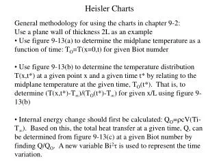
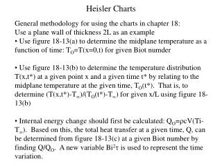
Heisler Charts. General methodology for using the charts in chapter 18: Use a plane wall of thickness 2L as an example Use figure 18-13(a) to determine the midplane temperature as a function of time: T O =T(x=0,t) for given Biot numder

E N D
Heisler Charts • General methodology for using the charts in chapter 18: • Use a plane wall of thickness 2L as an example • Use figure 18-13(a) to determine the midplane temperature as a function of time: TO=T(x=0,t) for given Biot numder • Use figure 18-13(b) to determine the temperature distribution T(x,t*) at a given point x and a given time t* by relating to the midplane temperature at the given time, TO(t*). That is, to determine (T(x,t*)-T)/(TO(t*)-T) for given x/L using figure 18-13(b) • Internal energy change should first be calculated: QO=rcV(Ti-T). Based on this, the total heat transfer at a given time, Q, can be determined from figure 18-13(c) at a given Biot number by finding Q/QO. A new variable Bi2t is used to represent the time variation.
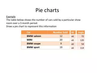
Unsteady HT Example A 2-m long 0.2-m-diameter steel cylinder (k=40 W/m.K, a=110-5 m2/s, r=7854 kg/m3, c=434 J/kg.K), initially at 400 C, is suddenly immersed in water at 50 C for quenching process. If the convection coefficient is 200 W/m2.K, calculate after 20 minutes: (a) the center temperature, (b) the surface temperature, (c ) the heat transfer to the water. • L/D=2/0.2=10, assume infinitely long cylinder • Check Lumped Capacitance Method (LCM) assumption: Bi=h(ro/2)/k=(200)(0.1)/2/40=0.25>0.1, can not use LCM, instead use Heisler charts. • Redefine Bi=hro/k=0.5
Example (cont.) (a) The centerline temperature: Bi-1=2, t=1.2, from figure 18-14(a), (TO-T)/(Ti-T)=0.38, (Ti-T)=400-50=350 Center line Temp. TO(t=20 min.)=(0.38)(350)+50=183 C. qo=0.38 t=1.2
Example (cont.) (b) The surface temperature should be evaluated at r/rO=1, for Bi-1=2, (T-T )/(TO-T)=0.78 from figure 18-14(b) 0.78 Bi-1=2
Example (cont.) Q/Qo=0.6 Bi2t=0.3