Download
1 / 23
230 likes | 240 Views
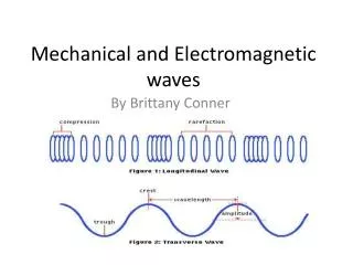
Physics 2113 Jonathan Dowling. Heinrich Hertz (1857–1894). Lecture 39: WED 26 NOV Ch.33 Electromagnetic Waves II. Electric Field:. Magnetic Field:. Wavenumber:. Wave Speed:. Angular frequency:. Vacuum Permittivity:. Vacuum Permeability:. Fig. 33-5. Amplitude Ratio:.

E N D
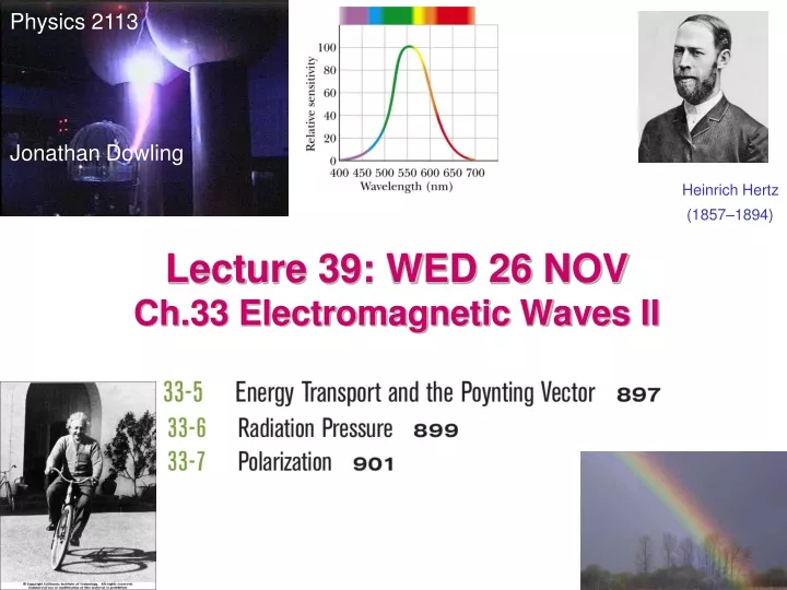
Physics 2113 Jonathan Dowling Heinrich Hertz (1857–1894) Lecture 39: WED 26 NOV Ch.33 Electromagnetic Waves II
Electric Field: Magnetic Field: Wavenumber: Wave Speed: Angular frequency: Vacuum Permittivity: Vacuum Permeability: Fig. 33-5 Amplitude Ratio: Magnitude Ratio: Mathematical Description of Traveling EM Waves All EM waves travel a c in vacuum EM Wave Simulation (33-5)
The Poynting Vector: Points in Direction of Power Flow Electromagnetic waves are able to transport energy from transmitter to receiver (example: from the Sun to our skin). The power transported by the wave and its direction is quantified by the Poynting vector. John Henry Poynting (1852-1914) For a wave, since E is perpendicular to B: In a wave, the fields change with time. Therefore the Poynting vector changes too!! The direction is constant, but the magnitude changes from 0 to a maximum value. Units: Watt/m2
EM Wave Intensity, Energy Density A better measure of the amount of energy in an EM wave is obtained by averaging the Poynting vector over one wave cycle. The resulting quantity is called intensity. Units are also Watts/m2. The average of sin2 over one cycle is ½: or, Both fields have the same energy density. The total EM energy density is then
Solar Energy The light from the sun has an intensity of about 1kW/m2. What would be the total power incident on a roof of dimensions 8m x 20m ? I = 1kW/m2 is power per unit area. P=IA=(103 W/m2) x 8m x 20m=0.16 MegaWatt!! The solar panels shown (BP-275) has dimensions 47in x 29in. The incident power is then 880 W. The actual solar panel delivers 75W (4.45A at 17V): less than 10% efficiency…. The electric meter on a solar home runs backwards — Entergy Pays YOU!
EM Spherical Waves The intensity of a wave is power per unit area. If one has a source that emits isotropically (equally in all directions) the power emitted by the source pierces a larger and larger sphere as the wave travels outwards: 1/r2Law! So the power per unit area decreases as the inverse of distance squared.
Received energy: Example A radio station transmits a 10 kW signal at a frequency of 100 MHz. At a distance of 1km from the antenna, find the amplitude of the electric and magnetic field strengths, and the energy incident normally on a square plate of side 10cm in 5 minutes.
Radiation Pressure Waves not only carry energy but also momentum. The effect is very small (we don’t ordinarily feel pressure from light). If light is completely absorbed during an interval Δt, the momentum Transferred Δp is given by F and twice as much if reflected. A Newton’s law: I Now, supposing one has a wave that hits a surface of area A (perpendicularly), the amount of energy transferred to that surface in time Δtwill be therefore Radiation pressure: [Pa=N/m2]
Ten-micron-diameter latex beads being propelled by a laser beam.
Solar Sails: Photons Propel Spacecraft! StarTrek DS9 NASA Concept NASA Demo
EM waves: polarization Radio transmitter: If the dipole antenna is vertical, so will be the electric fields. The magnetic field will be horizontal. The radio wave generated is said to be “polarized”. In general light sources produce “unpolarized waves”emitted by atomic motions in random directions.
EM Waves: Polarization Completely unpolarized light will have equal components in horizontal and vertical directions. Therefore running the light through a polarizer will cut the intensity in half: I=I0/2 When polarized light hits a polarizing sheet, only the component of the field aligned with the sheet will get through. And therefore:
Example Initially unpolarized light of intensity I0 is sent into a system of three polarizers as shown. What fraction of the initial intensity emerges from the system? What is the polarization of the exiting light? • Through the first polarizer: unpolarized to polarized, so I1=½I0. • Into the second polarizer, the light is now vertically polarized. Then, I2 = I1cos2(60o)= 1/4 I1= 1/8 I0. • Now the light is again polarized, but at 60o. The last polarizer is horizontal, so I3 = I2cos2(30o) = 3/4 I2 =3 /32 I0 = 0.094 I0. • The exiting light is horizontally polarized, and has 9% of the original amplitude.
Completely unpolarized light will have equal components in horizontal and vertical directions. Therefore running the light through first polarizer will cut the intensity in half: I=I0/2 When the now polarized light hits second polarizing sheet, only the component of the field aligned with the sheet will get through.
Plexiglas Model of Bridge Between Crossed Polarizers — Plastic Rotates Polarization Points of High Stress Show Up As Close Bands of Colors