Download

1 / 60

E N D
1. SE�AL DE TELEVISI�N
2. SE�AL DE TELEVISI�N
Se�al compuesta de v�deo
Sincronismo horizontal
Sincronismo vertical
3. SE�AL DE TELEVISI�N
4. SE�AL DE TELEVISI�N El sincronismo vertical se hace con una combinaci�n de 9 l�neas en las que se incluyen tres l�neas de preigualaci�n, tres de sincronismo vertical y tres de postigualaci�n.
Hoy todos estos sistemas no son necesarios. Los nuevos televisores tienen sistemas de sincronismo mucho m�s sofisticados que hacen innecesarias las se�ales anteriores. (S�lo son precisas en el momento de �enganche�.
5. Forma de una l�nea de televisi�n
6. Se�al de televisi�n Todos los tiempos de pedestales y sincronismos est�n perfectamente regulados por normas.
En la se�al de televisi�n se distinguen:
sincronismo con,
pedestal anterior.- separa la inf. de v�deo de los sincronismos
impulso de sincronismo.-
pedestal posterior.- separa la inf. de sincronismo de la de v�deo.
7. Se�al de televisi�n En TV Color, contiene el burst de croma.
se�al de v�deo:
Esta se�al contiene la informaci�n de una l�nea de televisi�n. Los puntos de amplitud cercana al nivel de sincronismo son puntos que en pantalla aparecen como puntos oscuros.
Los puntos que tienen una amplitud grande (muy separados de la se�al de sincronismo) tienen un gran brillo en pantalla.
8. Modulaci�n de la se�al de TV Modulaci�n AM; Banda Lateral Vestigial
Filtros suaves
Sonido modulado en FM
Bajas frec. de v�deo reforzadas
Se�al de croma con portadora suprimida (en TVC)
Segundo sonido NICAM (si existente)
9. NICAM stands for "Near Instantaneous Companded Audio Multiplex� NICAM currently offers the following possibilities, autoselected by the inclusion of a 3-bit type field in the data-stream:
One digital stereo sound channel.
Two completely different digital mono sound channels.
One digital mono sound channel and a 352Kbit/sec data channel.
One 704Kbit/sec data channel.
10. History NICAM (or to give it its full name, NICAM 728) was invented during the early 1980's by the BBC Research Centre, Kingswood Warren. It was first applied to the British "System I" 625 line PAL colour TV broadcasting system.
Theoretically, it could work with 525-line Systems M and N in the Americas, Canada and Japan.
11. Other stereo systems are in use in other parts of the world. The US and Canada use a system called BTSC, (for "Broadcast Television System Committee"). The BTSC system provides for another subcarrier to carry "Secondary Audio Program" (SAP), which is a mono audio feed independent of the main signal.
Apparently, BTSC is the only analogue system in the world for terrestrial or cable TV that can provide stereo audio for the main channel while also carrying a second channel in mono.
12. Modulaci�n de la se�al de TV
13. The Black-and-White TV Signal In a B/W TV, the screen is coated with white phosphor and the electron beam "paints" an image onto the screen by moving the electron beam across the phosphor a line at a time. To "paint" the entire screen, electronic circuits inside the TV use the magnetic coils to move the electron beam in a "raster scan" pattern across and down the screen.
14. Phosphor A phosphor is any material that, when exposed to radiation, emits visible light. The radiation might be ultraviolet light or a beam of electrons.
Any fluorescent color is really a phosphor -- fluorescent colors absorb invisible ultraviolet light and emit visible light at a characteristic color.
There are thousands of different phosphors that have been formulated. They are characterized by their emission color and the length of time emission lasts after they are excited.
15. Phosphor In a CRT, phosphor coats the inside of the screen. When the electron beam strikes the phosphor, it makes the screen glow. In a black-and-white screen, there is one phosphor that glows white when struck. In a color screen, there are three phosphors arranged as dots or stripes that emit red, green and blue light. There are also three electron beams to illuminate the three different colors together.
16. The Black-and-White TV Signal
The beam paints one line across the screen from left to right. It then quickly flies back to the left side, moves down slightly and paints another horizontal line, and so on down the screen, like this:
17. The Black-and-White TV Signal
18. The Black-and-White TV Signal In the previous figure, the blue lines represent lines that the electron beam is "painting" on the screen from left to right, while the red dashed lines represent the beam flying back to the left. When the beam reaches the right side of the bottom line, it has to move back to the upper left corner of the screen, as represented by the green line in the figure.
19. The Black-and-White TV Signal
When the beam is "painting," it is on, and when it is flying back, it is off so that it does not leave a trail on the screen. The term horizontal retrace is used to refer to the beam moving back to the left at the end of each line, while the term vertical retrace refers to its movement from bottom to top.
21. The CRT The steering coils are simply copper windings . These coils are able to create magnetic fields inside the tube, and the electron beam responds to the fields. One set of coils creates a magnetic field that moves the electron beam vertically, while another set moves the beam horizontally. By controlling the voltages in the coils, you can position the electron beam at any point on the screen.
22. The CRT
23. The CRT
24. The CRT
25. The Black-and-White TV Signal As the beam paints each line from left to right, the intensity of the beam is changed to create different shades of black, gray and white across the screen. Because the lines are spaced very closely together, your brain integrates them into a single image. A TV screen normally has about 480 lines visible from top to bottom.
26. Painting the Screen Standard TVs use an interlacing technique when painting the screen. In this technique, the screen is painted 60 times per second but only half of the lines are painted per frame. The beam paints every other line as it moves down the screen -- for example, every odd-numbered line. Then, the next time it moves down the screen it paints the even-numbered lines, alternating back and forth between even-numbered and odd-numbered lines on each pass.
27. Painting the Screen
The entire screen, in two passes, is painted 30 times every second. The alternative to interlacing is called progressive scanning, which paints every line on the screen 60 times per second
28. Painting the Screen Most computer monitors use progressive scanning because it significantly reduces flicker. Because the electron beam is painting all 525 lines 30 times per second, it paints a total of 15,750 lines per second. (Some people can actually hear this frequency as a very high-pitched sound emitted when the television is on.)
29. Painting the Screen The TV station or VCR therefore sends a well-known signal to the TV that contains three different parts:
Intensity information for the beam as it paints each line
Horizontal-retrace signals to tell the TV when to move the beam back at the end of each line
Vertical-retrace signals 60 times per second to move the beam from bottom-right to top-left
30. Video Signal A signal that contains all three of these components -- intensity information, horizontal-retrace signals, and vertical-retrace signals -- is called a composite video signal. A composite-video input on a VCR is normally a yellow RCA jack. One line of a typical composite video signal looks something like this:
31. Video Signal
32. Video Signal
33. Adding Color Color TV screen differs from a black-and-white screen in three ways:
There are three electron beams that move simultaneously across the screen. They are named the red, green and blue beams.
The screen is not coated with a single sheet of phosphor as in a black-and-white TV. Instead, the screen is coated with red, green and blue phosphors arranged in dots or stripes.
34. Adding Color On the inside of the tube, very close to the phosphor coating, there is a thin metal screen called a shadow mask. This mask is perforated with very small holes that are aligned with the phosphor dots (or stripes) on the screen.
The following figure shows how the shadow mask works:
35. Adding Color
36. Adding Color When a color TV needs to create a red dot, it fires the red beam at the red phosphor. Similarly for green and blue dots. To create a white dot, red, green and blue beams are fired simultaneously -- the three colors mix together to create white. To create a black dot, all three beams are turned off as they scan past the dot. All other colors on a TV screen are combinations of red, green and blue.
38. Color TV Signal
39. Color TV Signal A color TV signal starts off looking just like a black-and-white signal. An extra chrominance signal is added by superimposing a 3.579545 MHz sine wave onto the standard black-and-white signal. Right after the horizontal sync pulse, eight cycles of a 3.579545 MHz sine wave are added as a color burst.
40. Color TV Signal Following these eight cycles, a phase shift in the chrominance signal indicates the color to display.
The amplitude of the signal determines the saturation.
The following table shows you the relationship between color and phase:
41. Color TV Signal
42. Color TV Signal
A black-and-white TV filters out and ignores the chrominance signal. A color TV picks it out of the signal and decodes it, along with the normal intensity signal, to determine how to modulate the three color beams.
43. Getting the Television Signal Broadcast There are five different ways to get a signal into the TV set:
Broadcast programming received through an antenna
VCR or DVD player that connects to the antenna terminals
Cable TV arriving in a set-top box that connects to the antenna terminals
Large (6 to 12 feet) satellite-dish antenna arriving in a set-top box that connects to the antenna terminals
Small (1 to 2 feet) satellite-dish antenna arriving in a set-top box that connects to the antenna terminals
44. Getting the Television Signal: Broadcast A typical TV signal requires 4 MHz of bandwidth. By the time you add in sound, something called a vestigial sideband and a little buffer space, a TV signal requires 6 MHz of bandwidth.
Therefore, the FCC allocated three bands of frequencies in the radio spectrum, chopped into 6-MHz slices, to accommodate TV channels:
54 to 88 MHz for channels 2 to 6 (VHF-L)
174 to 216 MHz for channels 7 through 13 (VHF-H)
470 to 890 MHz for UHF, channels 14 through 83
45. Getting the Television Signal: Broadcast The composite TV signal described in the previous sections can be broadcast on any available channel.
The composite video signal is amplitude-modulated into the appropriate frequency, and then the sound is frequency-modulated (+/- 25 KHz) as a separate signal, like this:
47. The Television Signal
48. The Television Signal To the left of the video carrier is the vestigial lower sideband (0.75 MHz), and to the right is the full upper sideband (4 MHz). The sound signal is centered on 5.75 MHz. As an example, a program transmitted on channel 2 has its video carrier at 55.25 MHz and its sound carrier at 59.75 MHz. The tuner in your TV, when tuned to channel 2, extracts the composite video signal and the sound signal from the radio waves that transmitted them to the antenna.
49. Getting the Signal Large-dish satellite antennas pick off unencoded or encoded signals being beamed to Earth by satellites. First, you point the dish to a particular satellite, and then you select a particular channel it is transmitting. The set-top box receives the signal, decodes it if necessary and then sends it to channel 3 or 4.
50. Getting the Signal Small-dish satellite systems are digital.
The TV programs are encoded in MPEG-2 format and transmitted to Earth. The set-top box does a lot of work to decode MPEG-2, then converts it to a standard analog TV signal and sends it to your TV on channel 3 or 4.
51. Small-dish satellite systems
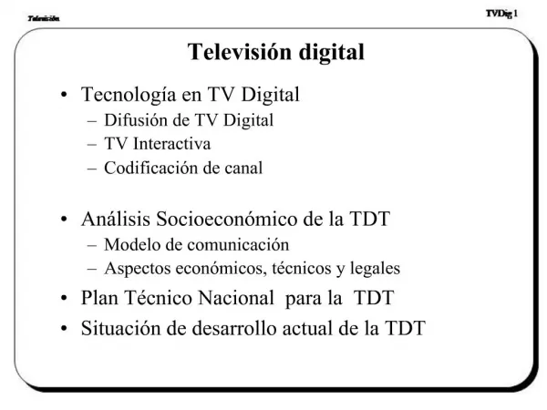
52. Digital TV Also known as DTV or HDTV (high-definition TV). DTV uses MPEG-2 encoding just like the satellite systems do, but digital TV allows a variety of new, larger screen formats.
The formats include:
480p - 640x480 pixels progressive
720p - 1280x720 pixels progressive
1080i - 1920x1080 pixels interlaced
1080p - 1920x1080 pixels progressive
53. Digital TV A digital TV decodes the MPEG-2 signal and displays it just like a computer monitor does, giving it incredible resolution and stability. There is also a wide range of set-top boxes that can decode the digital signal and convert it to analog to display it on a normal TV.
54. J.J. Thomson's Cathode Ray Tube In 1897, J. J. Thomson was refining experiments that dealt� with the glowing paths revealed when currents of electricity provided by high voltage sources passed through evacuated glass tubes. He was to eventually declare that these mysterious "cathode rays" were actually beams of electrons, small building blocks of matter.
55. J.J. Thomson's Cathode Ray Tube J.J. Thomson used results from cathode ray tube (commonly abbreviated CRT) experiments to discover the electron.
The image below is of J.J. Thomson and a cathode ray tube from around 1897, the year he announced the discovery of the electron.
56. J.J. Thomson's Cathode Ray Tube The image of a CRT used by Thomson in his experiments. It is about one meter in length and was made entirely by hand.
57. J.J. Thomson's Cathode Ray Tube The two plates about midway in the CRT were connected to a powerful electric battery thereby creating a strong electrical field through which the cathode rays passed.
Thomson also could use magnets, which were placed on either side of the straight portion of the tube just to the right of the electrical plates. This allowed him to use either electrical or magnetic or a combination of both to cause the cathode ray to bend.
58. J.J. Thomson's Cathode Ray Tube
59. Cathode ray tube
60. Cathode ray tube The cathode ray tube or CRT, invented by Karl Ferdinand Braun, is the display device used in most computer displays, video monitors, televisions and oscilloscopes. The CRT developed from Philo Farnsworth's work was used in all television sets until the late 20th century and the advent of plasma screens, LCDs and other technologies.
61. Cathode ray tube Scientists had discovered as early as the 1850's that when a magnet was held up next to the cathode ray tube, the beam would be deflected. This result can be seen in the following video.
Although the properties that J. J. Thomson defined for the electron are not quite what we know to be true today, his work with the discharge of electricity in gases earned him the 1906 Nobel Prize in Physics.