Download
1 / 20
200 likes | 321 Views
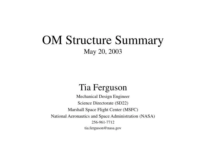
OM Structure Summary May 20, 2003. Tia Ferguson Mechanical Design Engineer Science Directorate (SD22) Marshall Space Flight Center (MSFC) National Aeronautics and Space Administration (NASA) 256-961-7712 tia.ferguson@nasa.gov. Outline. Level I Mechanical Interface Requirements

E N D
OM Structure SummaryMay 20, 2003 Tia Ferguson Mechanical Design Engineer Science Directorate (SD22) Marshall Space Flight Center (MSFC) National Aeronautics and Space Administration (NASA) 256-961-7712 tia.ferguson@nasa.gov
Outline • Level I Mechanical Interface Requirements • Level 1 Thermal Interface Requirements • Design Requirements • OM Design Summary • OM Weight Summary • Optical Subsystem Analysis • Integration, Testing and GSE • Mechanical Splinter Objectives
Level 1 Mechanical Interface Requirements • Two lenses with support structures will be provided separately. Metering structure and aperture plate will be provided by EUSO system • Lens outer diameter is 2500 mm • Outer ring structure is outside of optical path (2600 mm outside diameter) • Outer ring depth is 100mm • Each Lens structure will attach to EUSO system at three location around outer ring • Three interfaces will allow radial expansion of lens system • Design launch loads for lens systems: TBD • Minimum natural frequency of lens systems: TBD • Present design has natural frequency 16 Hz
OM Level 1 Thermal Interface • Current Design Baseline: Thermal control of OM is all passive, with temperature controlled by EUSO system • Operational temperature: system to maintain 10 +/- 10 C at all lens surfaces • Non-operational temperature: system to maintain 25 +/- 50 C at all lens surfaces • If required, heaters may be added to lens structure • thermostats, heaters and wiring provided by US • control and power provided by EUSO system • Any other adjustment between two lenses or focal plane and lenses to maintain focus needs to be considered at the EUSO system level
OM Design Requirements • The structure shall maintain alignment of optical components during operational phases by meeting error budget allocations • OM shall be operational following exposure to non-operational temperature extremes • OM shall survive launch and return to optical alignment once on-orbit • OM shall be capable of being tested with the optical axis in a vertical configuration in the ground environment • Mission Life: 3 years
Design Summary • Outer ring (1250mm radius at inner edge) • 50mm x 100mm x 2mm wall thickness • Monolithic lens, 15mm in center • Lens 1: 4717 radius (12.6 outer edge thickness) • Lens 2: -3496.5 radius (10.7mm outer edge) • 12 radial struts • 25mm x 25mm x 2mm wall thickness • One inner ring (937 mm radius at center) • 25mm x 50mm x 2mm wall thickness • 48 flexures • 24 on outer ring • 24 on inner ring • 9mm x 2mm cross-section, radially compliant B B SECTION B-B
Lens Structure Weight Summary Inner ring, 25 x 50 x 2 mm 5.5 kg 12 ribs, 25 x 50 x 2 mm 2.0 Outer ring, 50 x 100 x 2 mm 15.5 Flexures, 24+24 2.0 Rib attach brackets 3.5 Other brackets, estimate 7.5 Lens structure weight 36.0 Fasteners (<20%) 7.0 One lens structure assembly weight 43.0 Reserve, 25% 11.0 Total, one lens structure assembly 54.0
OM Total Weight Summary Lens 1 structure (with 25% reserve) 54.0 Lens 2 structure (with 25% reserve) 54.0 Total structure 108.0 2 Lenses (PMMA, 15mm) 178.2 Reserve on Lens material (<5%) 8.8 Total Lens 187.0 OM Total Mass 295.0
Analysis Finite Element Model (front) Finite Element Model (rear)
Integration, Testing, and GSE • Integration: will occur in 4619, with use of alignment stand and tooling to assure lens alignment • Structural testing: will be performed to certify the OM for flight, including structural load testing, modal survey testing, random vibration testing, acoustic testing of the components and subsystem, as appropriate. • Ground Support Equipment: alignment stand, lens handling frames, GSE aperture plate and metering structure for testing, shipping containers, protective covers for lenses
Objectives of Splinter • Define interface between lens structure and EUSO system • Discussion of error budget, and alignment maintenance • Thermal environment seen by the front lens • Discussion of baffle and lid design and impacts • Definition of loads and natural frequency requirements for lens systems • Presentation of details in analysis
Case 16: -Xlo (-1.8) Ymin (-9.94) -Zlo (-6.84)Lens Only, Out-of-plane (Z) Deflections (m)
Case 16: -Xlo (-1.8) Ymin (-9.94) -Zlo (-6.84)Lens Only, von Mises Stress (Pa) Load step 16 Lens only von Mises stress
Case 16: -Xlo (-1.8) Ymin (-9.94) -Zlo (-6.84)Frame Only, Out-of-plane (Z) Deflections (m)
Case 16: -Xlo (-1.8) Ymin (-9.94) -Zlo (-6.84)Frame Only, von Mises Stress (Pa)
Case 16: -Xlo (-1.8) Ymin (-9.94) -Zlo (-6.84)Flexure Only, von Mises Stress (Pa)