Download
1 / 11
110 likes | 186 Views
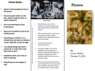
Neo-Picasso. Mike Park & Richard Lawrence. Overview. System Layout Objectives Design Approach Device Architecture Hardware Implementation. System Layout. Objectives. Reproduce computer drawing

E N D
Neo-Picasso Mike Park & Richard Lawrence
Overview • System Layout • Objectives • Design Approach • Device Architecture • Hardware Implementation
Objectives • Reproduce computer drawing • Design an algorithm that will calculate paths for the motion of the can base on a drawing made on a PC. • Send motor and actuator control signals from the PC to the microcontroller. • Design a PCB for our CPU, motor control, and actuator control. • Design Hardware • Lightweight can caddy • Motor mounts • 7’ – 10’ stands for motor mounts
Design Approach Path Generation • Adobe Illustrator provides Bezier curve coordinates • Our software reconstructs all the points along the curve
Design Approach String Length calculation • Software uses the generated (X,Y) coordinates in the following equations to determine how long each string should be to be at a certain (X,Y) point
Design Approach PC – Microcontroller Interface • To reduce the amount of data sent, our VB program calculates relative distances between adjacent points. • This data is formatted, and sent via serial port. • The data is stored in a register on the MSP.
Design Approach Motor Control • The data received from the PC is used to change the periods of the two PWM outputs that are going to the stepper controllers. By adjusting the PWM period, we adjust the speed of the motors relative to each other. • The stepper controllers take care of the sequential grounding of the stepper coils.
Hardware Implementation • MSP430F149 • Data from PC is used to change PWM period • PWM output connected to NJM3517 stepper controller • NJM3517 Stepper Controllers • 2 x Jameco 1.8 degree/step • Torque: 49 N/cm • 1.3A @ 4V • Trunk release actuator • Force: approximately 20lbs • 5A @ 12V