Download
1 / 17
170 likes | 295 Views
Current Aerial Mapping Sensor Test and Evaluation Activities and Results. American Society for Photogrammetry and Remote Sensing Annual Meeting Baltimore, Maryland March 2005. Why Laboratory Calibration Is NOT The Answer For Digital Aerial Systems. Diverse architectures

E N D
Current Aerial Mapping Sensor Test and Evaluation Activities and Results American Society for Photogrammetry and Remote Sensing Annual Meeting Baltimore, Maryland March 2005
Why Laboratory Calibration Is NOT The Answer For Digital Aerial Systems • Diverse architectures • Integration of cameras with other systems such as IMU and airborne-GPS equipment • Integration with software processes The government can neither build a single instrument to calibrate all systems nor build multiple instruments to cover every possible architecture.
In Situ Methods • In-situ methodologies can account for and measure sources of error in an imaging system under operating conditions. • Geopositional – Use checkpoints with known x, y, and z values • Spatial – Ground Sample Distance • Spatial - Modulation Transfer Function (MTF). Estimate MTF via: • Point Spread Function – point targets • Line Spread Function – pulse targets or edge targets • Radiometric • Absolute Radiometry • Relative Radiometry
The Goals of the C2V2 Group • Long-Term: Federal Civil Policies, Standards, and Guidelines for Digital Aerial Imaging Systems • Short-Term: Remove the Barriers that Prevent the Use of Digital Aerial Imaging Systems
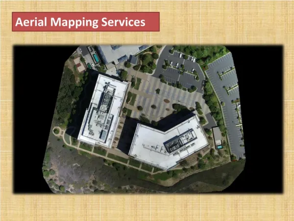
In the Interim… • Product Characterization: Evaluate products and compare results to product specifications. • An interim solution until policies, standards, and guidelines can be emplaced • Jointly conducted by USGS and NASA • Operators submit orthoimagery of Stennis Space Center ‘Fee Area’ using Ground Sample Distances and elevation sources they would use to fill government contracts
Product Characterization: Pros • Straightforward implementation • Product specification driven – not constrained by system architecture • Each test increases experience with these systems and their datasets; the more we learn, the better our policies, standards, and guidelines will become
Product Characterization: Cons • Cost to both operators and government • Voluntary participation • ‘Benchmark’ type test is not an indicator of long-term or sustained performance • Orthoimage compilation process can introduce error into the product that does not originate with the imaging system
Evaluation Components • Geopositional – Compare measured coordinates of checkpoints in the orthoimagery to surveyed values • Spatial – Perform a Relative Edge Response analysis on imagery of edge targets. This is a technique that estimates the Line Spread Function of an imaging system • Radiometric – Deploy special tarps and other instruments
Geopositional • Use checkpoints to assess imagery • Geodetic Targets • Manhole Covers
Image area selected for spatial response measurement in Northing direction Spatial • Use Edge Targets to evaluate Relative Edge Response (RER) The RER is a geometric mean of normalized edge response differences measured in two directions of image pixels (X and Y) at points distanced from the edge by -0.5 and 0.5 GSD The RER estimates effective slope of the imaging system’s edge response because distance between the points for which the differences are calculated is equal to the GSD
Radiometric • Absolute correction: Correct radiance or reflectance should be measured or converted by using the sensor calibration data, the sun angle and view angle, atmospheric models and ground truth data • Relative Correction: Relative correction is to normalize multi-temporal data taken on different dates to a selected reference data at specific time • Typical techniques: • Adjustment of average and standard deviation values • Conversion to normalized index: for example the normalized difference vegetation index (NDVI) • Histogram matching: the histograms per band and/or per sensor are calculated and the cumulative histogram with cut-offs at 1% is determined, where y is reference data and x is data to be normalized
Current Status • Seven evaluations completed • Applanix DSS 300 operated by Emerge – Geopositional Only • Space Imaging Digital Airborne Imaging System operated by Space Imaging • Leica Geosytems ADS40 operated by EarthData International • IKONOS Satellite operated by Space Imaging • Zeiss/Intergraph Digital Mapping Camera operated by AERO-METRIC, Inc. • M7 Visual Intelligence AirReconV operated by M7 Visual Intelligence – Geopositional Only
Current Status (Continued) • Three evaluations pending • Leica Geosystems ADS40 operated by Northwest Geomatics • Zeiss/Intergraph Digital Mapping Camera operated by 3001, Ltd. (Draft report completed – review and release pending) • Vexcel UltraCam-D operated by Sanborn • Interest from other sensor operators: DeLorme; Digital Aerial Solutions; GeoVantage; Horizons, Inc.; Photo Science, Inc.; Spectrum Mapping; and Titan
USGS Specifications for Orthoimagery *RMSE and CE values are in meters • Specifications sources: • 1.00M: USGS Orthoimagery Standards • 0.50M, 0.25M, 0.15M: ASPRS Large Scale Mapping Guidelines • 0.30M: Product Specifications for High Resolution Urban Area Imagery for NGA
Issues • Diversity: Operator capabilities and products vary; it is hard to make a meaningful comparison of one operator’s product to another • Variety of GSDs: six-inch to one meter • Variety of image types: panchromatic, natural color, CIR. • Variety of elevation data sources: USGS DEMs, LiDAR, ISTAR, image autocorrelation • Relative Edge Response • Estimate sensitive to image re-sampling and image saturation • What is the significance of the RER value? • Radiometry • No evaluations of radiometry for airborne systems • Difficult to arrange due to high cost and level of coordination.