Download
1 / 17
180 likes | 374 Views
Super Star Trackers for MAXIM and Stellar Imager. Several future missions will require a stable reference at the level of 30 as MAXIM Pathfinder, Stellar Imager Eventually, missions will need a stable reference at the level of 30 nano-arcsecs! MAXIM, Gamma ray lens, ARISE

E N D
Super Star Trackers for MAXIM and Stellar Imager • Several future missions will require a stable reference at the level of 30 as • MAXIM Pathfinder, Stellar Imager • Eventually, missions will need a stable reference at the level of 30 nano-arcsecs! • MAXIM, Gamma ray lens, ARISE • Must be held stable for hours~days • Absolute astrometry not necessary • Should also be useful for Beacon centroiding in the formation flying solution • Replace SIM modules
Contacts • Keith Gendreau/662 • MAXIM • Ken Carpenter/681 • Stellar Imager • Kate Hartman/420 • MAXIM • Jesse Leitner/571 • MAXIM, SI • Landis Markley/571 • MAXIM
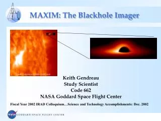
MAXIM Pathfinder Overview http://maxim.gsfc.nasa.gov • Objectives • Demonstrate X-ray interferometry in space as pathfinder to full up MAXIM • Image with 100 micro-arc second resolution using a 1-2 m baseline • 1000 times improvement on Chandra • Coronae of nearby stars • Jets from black holes • Accretion disks • Two spacecraft flying in formation: • Telescope spacecraft with all the optics • 300 micro arc sec pointing control • 30 micro arc sec knowledge • “Detector spacecraft” positioned 50-500 km 10 m and laterally aligned 2 mm from Telescope spacecraft to make fringes well matched to detector pixels • Detector and optics fit within medium class launch vehicle (e.g., Delta IV H) Detector Spacecraft L=50-500 km! Optic Spacecraft
In 1-D we have: 3 unknowns: d,o, dx But laser interferometers Only give us 2 measurements: Dred, and Dgreen Two Laser interferometers can make the two spacecrafts virtually rigid- but we still need a tie-in to the celestial sphere-> we still need a star tracker. Interference pattern from optics space craft laser interferometer Dred o dX Interference Pattern from Detector Space craft laser interferometer Dgreen d
Using a “Super Startracker” to image reference stars and a laser beacon. Super Star Tracker Sees both Reference stars and the beacon of the other space craft. It should be able to track relative drift between the reference and the beacon to 30 microarcseconds. o dX Laser Beacon with Divergence > qo Must control Optics space craft to have tilts less than the laser beacon divergence or such that the beacon moves by less than an angular resolution element over the system focal length-which ever is smaller d
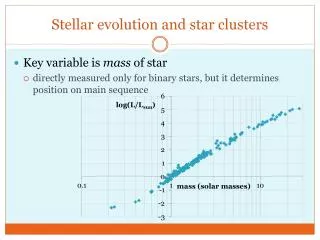
Strawman Idea • Make a star tracker with a big enough aperture so that in a reasonable amount of time, we can collect enough photons from a star to centroid the stars position to ~30as • #photons/sec on an aperture “r” cm across ~107r210m/5 • Diffraction limit for “r” @ wavelength : ~r • Position determination with N photons: ~(r N) • Position determination with a magnitude “m” star in “t” seconds • ~10-4 r2 10m/5/ t radians • Have 2 or more of these to compensate for proper motion, etc… • Would be great for seeing a beacon on another space craft • Consider the “Quartz Telescope” of GP-B • Will use 5th mag star HR5110 • 5” telescope-> 0.1 marcsecs
Some Details • There are a limited number of stars bright enough to do this, so high precision gimbals (30as) are needed to point the SST or a pick-off mirror at available stars. • What kind of focal plane will this have? • Is it a CCD? What will the FOV be? Beware of full well capacity!! • How stable will/should the platform be? • NGST will use bandwidths of 1-10 Hz or so • Use of “Coarse” Star trackers to get SST close. How to hand off coarse to fine • Registration of the Fine tracker • Use of Gyroscopes to make use of fainter stars…? • How fine can we centroid? 1/100th of a pixel? More? • Stars move • Aberration of light (can be ~20 arcsec in a year…or 40 microarceseconds in a minute!) • Parallax effects can be as large as 30 microarcseconds a day for stars 0.5 kpc away • Proper Motion in Galactic Potential • Wobble from planets • Motion of features on the stars • Other?
A non-professionals view of the dependencies Mirror Aperture See a Bright Enough Reference Star Super Gyros Pixel Size How Well Can Centroid? Field Of View Stable Reference At 30mas Level For ~1 Day Array Size Accommodate Stellar Motion Due to Parallax and Stellar Aberration Gimbals
Detector Options: Imagers • CCD • Gimbal requirements softened if wide enough FOV • How small a pixel? • Do we need to worry about full well capacity of CCD? • Power? • Would allow us to track beacon on other satellite • Lifetime? Radiation Hardness? (SI) • CIDs • Too noisy now? • Others?
Detector Options: Non-Imagers • Quad Cell (Quadrant Detector) • Requires gimbal • Low power • Limited use.. Track a star or a beacon. • Lateral Effect Photodiode • FOV Like a CCD- but less power • Not really imaging • Accurate enough?
Super Gyroscopes? • What kind of gyroscope will help us to descope the telescope size? • Need 30 arcsec resolution and drift over tracker integration time • Mechanical Gyroscopes • Still the most accurate gyros available • GP-B Gyro has a drift of 1/3 microarcsecond/day!! • Needs cryogen • Maybe a future ISAL run where we look at using high Tc superconductors
Super Gyroscopes? • Non-Mechanical Gyroscopes • Kilometric Optical Gyroscope (KOG) • Uses Sagnac Effect with light- precision ~/perimeter • For = 630 nm, 4 km perimeter should be adequate • Maybe have lock-in problem for “0” rotational velocity • Proposed for StarLight, but cost and technical issues • Atomic Interferometric Gyroscope • Sagnac Effect with reduced wavelength • “Way” out there, but see the ESA mission concept:”Hyper” http://sci.esa.int/pdf/hyper.pdf (200 Watts, 200 kg)
Goals of this Study • Get a good handle on mass/power/cost/size for input into an IMDC study for SI or MAXIM Pathfinder, where 30 microarcsecond Line-of-Sight knowledge is needed. • At least better than the WAG we have made in the past IMDC runs • Define “other” requirements- jitter, thermal,.. • Understand the scaling laws to make this eventually work for a more complex mission needing 30 nas line-of-sight knowledge • Identify required technologies: • 1) to make possible • 2) to make cheaper • See what studies are currently under way (eg look through NASA Technology Inventory,…) Where does this fit in? • Eg. This should also be a part of the VISNAV system • Bring some awareness of these types of issues for our more challenging imaging missions to GSFC people. • Better define the problem- the usual “scientist does not quite know how to describe the needs to engineer” difficulty….
Way Out Ideas Rigel Regulus • Free flying star tracker? Vega Star Tracker Spacecraft stays pointed so as to capture a strategically chosen collection of guide stars. It is “virtually” rigidly connected to the interferometer array via laser interferometers. Advantages: can make reasonable sized star trackers for bright stars, simple ACS system, simple mechanical structure multi-mission… possible part of the L2 public utilities… Disadvantages: Need satellite bus, com system, power, etc… How does this trade against having it attached to one satellite In the array?
Calibration: GP-B Solution Aberration to the Rescue: Nature's Measuring Rod The gyroscope and telescope output signals are not angles but voltages. That fact raises two issues. First, how to match the readouts -- so that a given spacecraft pointing error causes identical voltage changes in each. Second, how to calibrate the final subtracted output -- so that observed voltage can be translated into an angle, the angle in milliarc-seconds between the gyro axis and the line to Rigel. Matching is achieved by a technique known as dither. The spacecraft is forced to swing slowly through a small angle back and forth across the line to Rigel, and the resultant oscillatory signals in the two readouts are adjusted until equal. Calibration would be extraordinarily difficult were it not that Nature herself supplies the means through the phenomenon known as aberration of starlight. As the satellite orbits the Earth, and the Earth orbits the Sun, the apparent position of the star, tracked by the telescope, becomes periodically displaced by exactly known amounts (+-5 arc-seconds during the orbit, +-20.148 arc-seconds during the year). These displacements serve as "measuring rods" for the relativity signals. So a wandering motion, which to its discoverer James Bradley in 1729 seemed disturbingly aberrant, saves Gravity Probe B. Surprisingly, it is only by an application of the equations of special relativity (a step not taken until 1980) that the aberration can be determined to the precision needed. Einstein would have liked that point. http://www.onr.navy.mil/02/c0241e/GPB6.htm