Download
1 / 27
270 likes | 376 Views
NA62 computing model update. Paolo Valente – INFN Roma [ Acknowledgements to B. Panzer-Steindel, M. Lamanna, A. Di Girolamo]. Requirements: data volume/1. SPS duty-cycle: 9.6 s flat top/27.6 s Trigger rates/latencies: L0: 1 MHz/0.1 ms L1: 100 kHz / 1 s L2: 15 kHz / 27.6 s

E N D
NA62 computing model update Paolo Valente – INFN Roma [Acknowledgements to B. Panzer-Steindel, M. Lamanna, A. Di Girolamo] NA62 collaboration meeting
Requirements: data volume/1 • SPS duty-cycle: 9.6 s flat top/27.6 s • Trigger rates/latencies: • L0: 1 MHz/0.1 ms • L1: 100 kHz/1 s • L2: 15 kHz/27.6 s • Event size: 30 kB • Zero-suppressed LKr (130001000 cells, 185 kB/13=14 kB) • All other detectors: 15 kB • RAW data: 13.5 TB/day • Band-width to storage: 150 MB/s • 150k events/burst=4GB/burst NA62 collaboration meeting
Requirements: data volume/2 • L3 • The (possible) filtering of events after L2 trigger and reconstruction and before permanent storage • A single parameter in the estimates: f=reduction fraction, 0<f≤1 • Running time: 100 full days (100% efficiency), i.e. 300k bursts • RAWdata: f×13 TB/day×100 days=f×1.2 PB/year • RECOnstructed data assumed to have approximately the same size of RAW data (in the end they could be even larger) • THIN ? • As a comparison, in 2007: • 120 days of data taking, 450k bursts of 14,4 s 60%live-time • 55k events/burst, 11 kB/event 600 MB/burst, 40 MB/s band-width • 300 TB unfiltered total RAW data • f=0.3 90 TB after L3 filtering NA62 collaboration meeting
Computing resources: summary • Tapes • 1.2 PB/year RAW + reconstructed data (RECO) • RECO size can be optimized, but expect at least same size as RAW • Deletion policy (How many versions? Where to keep them?) • Difficult to expect less than 2 PB/year • Disk • Essentially driven by processing/reprocessing needs • Depends on the computing model • If one full data-set to be kept on disk,1-2 PB • CPU • Full reconstruction: O(1) HS06s/event, 5kevents/s = 5kHS06 = O(500) cores ×(safety factor=2) = 10 kHS06 • Really need to check this number NA62 collaboration meeting
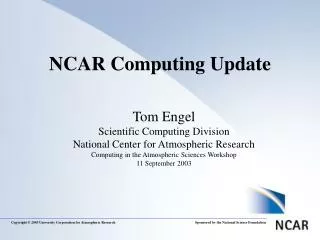
Comparison with LHC experiments 5 (without LKr) 3x10⁴ 150 (5×10³) LV-0 106 LV-1105 2 NA62
Comparison with LHC experiments NA62 • L2 output rate = 5 kHz (averaged over the spill) • 30 machines = 720 cores • Event size ≅ 30 kB • RAW volume/year = 1.2 PB LHCb • L2 output rate = 3 kHz(design) 5 kHz • 25 k processes • Event size ≅50 kB • RAW volume/year = 1 PB • AOD = 750 kB/event (200 Hz) • DST = 150 kB/event • mDST = 10 kB/event ATLAS/CMS • L2 output rate = 0.5/0.35 kHz • Event size ≅ 0.5 MB/1.5 MB • RAW volume/year = 5 PB • ESD = 2 MB/1 MB • AOD = 300 kB ATLAS
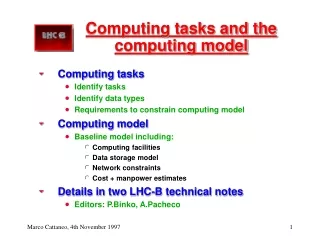
LHC computing models (Original definitions of LHC experiments computing models) MONARC model • Dedicated networks • LHCOPN • Dedicated to T0 to T1 and T1 to T1 • LHCONE • Dedicated to T2’s connection • Tier-0 • Primary computing infrastructure at CERN (CPU + Disk + Mass Storage) • State of the art networking • connectivity to the experiments • connectivity to the Tier-1 centers • Requirements for custodial storage of datasets • RAW data archive • Archive of reconstructed data and AOD • Service level: 24×7 service • Tasks: Prompt Reconstruction, data archiving, prompt alignment and calibration, transfer of RAW/RECO to Tier-1’s • at CERN • Tier-1 • Computing infrastructure (CPU + Disk Storage + Mass Storage) on the Grid • State of the art networking • 10 Gb/s connectivity to CERN on OPN, connectivity to other Tier-1’s • Connectivity to Tier-2’s on LCHONE • Requirements for custodial storage of datasets • RAW data must remain accessible throughout the lifetime of the LHC • Long-term access to RECO/SIMU and analysis datasets • National (regional) support role including training and user support • Service level: 24×7 service • Tasks: Reprocessing, analysis skims, archiving • At national labs, main universities • Tier-2 • Simulation • User analysis
LHC experiments ATLAS [original] CMS LHCb ALICE
Evolution of LHC computing models • [Some] motivations for original MONARC model • The network was a very limited resource, potentially a bottleneck • Need a hierarchical mass storage, cannot keep everything in a local disk space • Disk/Tape hierarchy • Job runs “close” to data, achieving efficient CPU utilization • Need a structured and predictable data utilization • What happened as soon as LHC started? • Data transfers between sites demonstrated to be more reliable than predicted • The WAN bandwidth is comparable with the backbone available at LAN level • Some Tier-2 sites are larger then some Tier-1 sites • Geographically distributed job submission and resource usage are working well • Hierarchical mass storage system is complex to manage and requires effort • Regional transfer of data is basically broken • Evolution of LHC computing models from a hierarchical mass storage system to a full mesh/peer-to-peer • Reduced latency in data transfers • Increased working efficiency • Possibility to remotely read data when needed without dramatic impact on CPU efficiency • Hiding local data issues/failures to the users
LHC experiments data types (Original definitions of LHC experiments computing models) • RAW: data from the detector • Input into the reconstruction at the Tier-0 • RECO: primary output of the reconstruction from RAW data • AOD: reduced event data for analysis • TAG: event-level metadata • SIMU: Simulated data that has been reconstructed • Also contains generator information and MC-truth
NA62 data flow and types RECO ? RAW THIN More formats?... NTUP ?
Data stripping • Different types of RECO data reduction: • Filtering/Skimming • Only events that are interesting for the specific types of calibration/analysis are kept. • Trimming • Removal of entire containers or top-level data objects from all events. For example, one might remove the calorimeter cells for performance studies of track reconstruction • Thinning • Removal of individual objects from a container. For example, to study efficiencies for electron and photon reconstruction one needs to keep only calorimeter cells associated to a track. • Slimming • Removal of parts of an object. For example, one might remove an error matrix from tracking algorithms, when this particular piece of information is not needed for the specific analysis/task ≈ Compact SuperCompact
Event building and storage CERN NA62 farm Tier-0 Tapes Event building Disk pool Farm storage 1. Events are built in the PC farm after L2 selection, the RAW data files are recorded on the farm disk server(s) 2. RAW files are copied to a large disk pool in the CERN data center 3. RAW files are migrated to tape (custodial copy) and marked for deletion on the farm disks - The farm storage should be capable of holding at least 48h of continuous data taking (>27 TB), but of course it will be needed also for services, and for holding calibration or dedicated data. - The link to the CERN data center should not generate back-log: the present connection at 1 Gb/s should be upgraded RAW
Reconstruction CERN NA62 farm Tier-0 Tapes Disk pool Reconstruction 4. Reconstruction is started taking as input the RAW files on the disk pool, RECOnstructed files are stored on the disk pool 5. RECO files are also migrated to tape - In principle, once successfully reconstructed and migrated to tape, the RAW files could be deleted also from the disk pool, but we want to keep/distribute RAW files for subsequent re-processing RAW RECO-1
Data distribution CERN NA62 farm Institutes Tier-0 Tier-1 A Tapes xA% Disk pool Disk x0% xB% Tier-1 B Disk • 6. The RAW data-set is partially transferred to the Tier-1’s and partially kept at the Tier-0 • 7. RECO files are also distributed (for analysis) • - The entire data-set is shared between the Tier-0 (x0%) and the Tier-1’s. • - The share between sites can be adjusted, while ensuring: x0 + xA + xB + … = 100% • The details of RECO files distribution will depend on the requests of the analysis groups • 8. RECO files are THINned for analysis RAW RECO-1
Re-processing CERN NA62 farm Institutes Tier-0 Tier-1 A Tapes Reco xA% Disk pool Disk x0% Thinning Thinning Tier-1 B Reconstruction Reco xB% Disk Thinning 9. Re-processing is started from the RAW (of current year) on disk at the Tier-0 and at Tier-1’s 10. RECO-2,3… files are migrated to tape 11. RECO files THINning RAW As an option, the Tier-1’s can take part to the first pass of the reconstruction, of course as soon as the files are successful copied. In this case, the reconstruction starts immediately at Tier-0 only on a fraction x0% of the RAW, while each of the RAW files of the remaining 100%-x0% will be reconstructed upon successful transfer to the remote site, RECO files can be transferred back to CASTOR, if necessary RECO-2, …
Analysis CERN NA62 farm Institutes Tier-0 Tier-1 A Tapes xA% Disk pool Disk x0% Tier-1 B xB% Disk - Analysis is performed at the Tier-2’s Tier-2 Tier-2 Tier-2 Tier-2 Analysis Analysis Analysis Analysis THIN-1, …, THIN-n Analysis Analysis
CERN NA62 farm Institutes Tier-0 Tier-1 A Tapes Reco Event building xA% Disk pool Disk Farm storage x0% Thinning Thinning Tier-1 B Reconstruction xB% Disk • Not shown possible exchanges of: • THIN between T1’s • THIN to T2 from different T1’s • Analysis output to T1’s Thinning Tier-2 Tier-2 RAW Tier-2 Tier-2 RECO-1 Tier-2 RECO-2, … THIN-1, …, THIN-n Analysis Analysis
General comments (in random order)/1 • “Tapes” [today] is CASTOR • “Disk pool” could be EOS • The migration to “tapes” is performed through a disk-cache in front of the tape drives, so it is from disk to disk. Deletion policy should be decided by the data handler, upon successful completion of the subsequent steps: • e.g. a file can be marked for deletion on the farm disks once successfully copied to the disk-cache of CASTOR and kept on the EOS disk until migrated to tape AND the RECO is produced by the reconstruction • Tapes drives are currently O(100) at CERN… the assigned drives are adjusted automatically, we need to make sure that the drives for NA62 can scale with the need of data taking • The solid lines representing file “transfer” to Tier-1 and Tier-2 data center from analysis tasks or processing/reprocessing can be interpreted in two alternative/interchangeable ways: • The files are actually transferred (via gridftp /srm/xrdcp/http copy) • Remote I/O also possible (e.g. a THIN file on a Tier-1 can be accessed by an analysis task running in a Tier-2 WN without copying the file) • Analysis tasks output is not represented: it is probably ok to keep the output files where they are produced. • An user quota on the EOS big disk pool is foreseen, but the main purpose of the EOS space should be: • to ensure that the processing of data is performed from disk • to allow efficient reprocessing • The size of the main disk pool should be such to keep a consistent fraction of one-year data-taking available. The share between sites x0, x1A, x1B, … should be adjusted in order to guarantee that at least an entire data-set (= 1 year) is available on disk.
General comments (in random order)/2 • In the model with immediate distribution of RAW files to the off-CERN sites, the off-site data centers de facto will share part of the Tier-0 task (first-pass reconstruction) and, in the subsequent stages, CERN will participate to re-processing as one of the Tier-1’s. • Each of the Tier-0/1 centerswill have a given fraction of RAW data to process or re-process. • This should make the use of resources for reconstruction more efficient, and processing and following re-processing productions more similar, the only difference being the need of restaging from tape to the disk pool if one wants to re-process a data-set different from the current year • The data-quality and physics monitoring can be performed on the x0% of the entire data, on the freshly reconstructed data at CERN. In this case, the fraction x0 of CERN-resident RAW should take into account the need for a prompt monitoring of data • In the scheme, RECO files are stored to tape. This has to be carefully tuned. ATLAS e.g. deletes all ESD files (apart ExpressStream for monitoring) and only saves AOD. • First of all, a deletion policy can be defined, e.g. we can keep on tape only version n and n-1, until reprocessing n+1 is completed • Another possibility is to avoid copying back to CERN CASTOR the RECO files produced at the other Tier-1 centers, using local tape systems. • In general, avoidcross-distribution of RECO files
General comments (in random order)/3 • Assume 1 burst 1 RAW file 1 RECO file 1 THIN file • Files up to 4 GB, atleast for RAW and RECO • THIN fileshopefullysmaller, butprobably1 burst 1 file still OK • Calibrations • Performed typically from RECO • Calibration tasks could run automatically once a given amount of data is reached • To be performed at the T0 and/or T1’s • In order to optimize resources, consider the possibility of: • Perform prompt reconstruction only the fraction of data needed for Data Quality/Physics monitoring at pass-1 • Run full data-set reconstruction only at pass-2+, once calibrations are OK • Convenient only if we feel that at least 1 re-processing is needed • Probably not OK for 2014 run
Summarizing Baseline design: • RAW stored and reconstructed (pass-1) at CERN Tier-0, copied to Tier-1 centers • RECO distributed at Tier-1’s and thinned • Re-processing for pass-2+ at Tier-1’s • Thinned data distributed to Tier-2 centers for user analysis, also used for Monte Carlo production Modified in order to: • Distribute immediately RAW files to Tier-1’s keeping a fraction at the CERN disk pool. All RAW files are in any case kept on tape at CERN (custodial copy). • Use CERN+Tier-1 centers on the same footing for pass-1 processing and re-processing and for THIN production • Avoid cross-distribution of RECO files between the Tier-1’s We end up with the following scheme…
CERN NA62 farm Institutes Tier-1 A Tier-0 Tapes Reco Event building xA% xA% Disk pool Disk Tapes Farm storage x0% Thinning xB% Thinning Tier-1 B Reconstruction Reco xB% Disk • Not shown possible exchanges of: • RECO/THIN between T1’s • THIN to T2 from different T1’s • Analysis output to T1’s Tapes Thinning Tier-2 Tier-2 Tier-2 Tier-2 Tier-2 Tier-2 RAW Tier-2 RECO-1, …, RECO-n THIN-1, …, THIN-n Analysis Analysis Analysis Analysis Analysis Analysis Analysis
Ok, let’s try to put some labels… CERN-PROD RAL-LCG2 NA62-FARM Tapes Reco Event building xA% xA% Disk pool Disk Tapes Farm storage x0% Thinning xB% Thinning INFN-T1 Reconstruction Reco xB% Disk • Not shown possible exchanges of: • RECO/THIN between T1’s • THIN to T2 from different T1’s • Analysis output to T1’s Tapes Thinning BelGrid-UCL INFN-PISA … more sites RAW INFN-FRASCATI UKI-NORTHGRID-… RECO-1, …, RECO-n THIN-1, …, THIN-n Analysis Analysis Analysis Analysis