Download
1 / 73
750 likes | 986 Views
Lecture 19 Multimedia Networking ( cont ). CPE 401 / 601 Computer Network Systems. slides are modified from Dave Hollinger. slides are modified from Jim Kurose, Keith Ross. 7.1 multimedia networking applications 7.2 streaming stored audio and video

E N D
Lecture 19Multimedia Networking (cont) CPE 401 / 601 Computer Network Systems slides are modified from Dave Hollinger slides are modified from Jim Kurose, Keith Ross
7.1 multimedia networking applications 7.2 streaming stored audio and video 7.3 making the best out of best effort service 7.4 protocols for real-time interactive applications RTP,RTCP,SIP 7.5 providing multiple classes of service 7.6 providing QoS guarantees Chapter 7 outline 7: Multimedia Networking
PC-2-PC phone Skype PC-2-phone Dialpad Net2phone Skype videoconference with webcams Skype Polycom Going to now look at a PC-2-PC Internet phone example in detail Real-time interactive applications 7: Multimedia Networking
Interactive Multimedia: Internet Phone Introduce Internet Phone by way of an example • speaker’s audio: alternating talk spurts, silent periods. • 64 kbps during talk spurt • pkts generated only during talk spurts • 20 msec chunks at 8 Kbytes/sec: 160 bytes data • application-layer header added to each chunk. • chunk+header encapsulated into UDP segment. • application sends UDP segment into socket every 20 msec during talkspurt 7: Multimedia Networking
Internet Phone: Packet Loss and Delay • network loss: IP datagram lost due to network congestion (router buffer overflow) • delay loss: IP datagram arrives too late for playout at receiver • delays: processing, queueing in network; end-system (sender, receiver) delays • typical maximum tolerable delay: 400 ms • loss tolerance: depending on voice encoding, losses concealed, packet loss rates between 1% and 10% can be tolerated. 7: Multimedia Networking
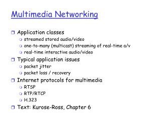
client reception constant bit rate playout at client variable network delay (jitter) buffered data client playout delay Delay Jitter • consider end-to-end delays of two consecutive packets: difference can be more or less than 20 msec (transmission time difference) constant bit rate transmission Cumulative data time 7: Multimedia Networking
Internet Phone: Fixed Playout Delay • receiver attempts to playout each chunk exactly q msecs after chunk was generated. • chunk has time stamp t: play out chunk at t+q . • chunk arrives after t+q: data arrives too late for playout, data “lost” • tradeoff in choosing q: • large q: less packet loss • small q: better interactive experience 7: Multimedia Networking
Fixed Playout Delay • sender generates packets every 20 msec during talk spurt. • first packet received at time r • first playout schedule: begins at p • second playout schedule: begins at p’ 7: Multimedia Networking
Adaptive Playout Delay (1) • Goal:minimize playout delay, keeping late loss rate low • Approach:adaptive playout delay adjustment: • estimate network delay, adjust playout delay at beginning of each talk spurt. • silent periods compressed and elongated. • chunks still played out every 20 msec during talk spurt. dynamic estimate of average delay at receiver: where u is a fixed constant (e.g., u = .01). 7: Multimedia Networking
Adaptive playout delay (2) • also useful to estimate average deviation of delay, vi : • estimates di , vi calculated for every received packet • but used only at start of talk spurt • for first packet in talk spurt, playout time is: • where K is positive constant • remaining packets in talkspurt are played out periodically 7: Multimedia Networking
Adaptive Playout (3) Q: How does receiver determine whether packet is first in a talkspurt? • if no loss, receiver looks at successive timestamps. • difference of successive stamps > 20 msec -->talk spurt begins. • with loss possible, receiver must look at both time stamps and sequence numbers. • difference of successive stamps > 20 msec and sequence numbers without gaps --> talk spurt begins. 7: Multimedia Networking
Forward Error Correction (FEC): simple scheme for every group of n chunks create redundant chunk by exclusive OR-ing n original chunks send out n+1 chunks, increasing bandwidth by factor 1/n. can reconstruct original n chunks if at most one lost chunk from n+1 chunks playout delay: enough time to receive all n+1 packets tradeoff: increase n, less bandwidth waste increase n, longer playout delay increase n, higher probability that 2 or more chunks will be lost Recovery from packet loss (1) 7: Multimedia Networking
Recovery from packet loss (2) • 2nd FEC scheme • “piggyback lower quality stream” • send lower resolutionaudio stream as redundant information • e.g., nominal stream PCM at 64 kbpsand redundant streamGSM at 13 kbps. • whenever there is non-consecutive loss, receiver can conceal the loss. • can also append (n-1)st and (n-2)nd low-bit ratechunk 7: Multimedia Networking
Interleaving chunks divided into smaller units for example, four 5 msec units per chunk packet contains small units from different chunks if packet lost, still have most of every chunk no redundancy overhead, but increases playout delay Recovery from packet loss (3) 7: Multimedia Networking
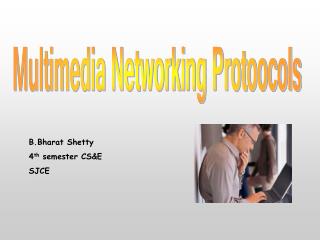
Content replication challenging to stream large files (e.g., video) from single origin server in real time solution: replicate content at hundreds of servers throughout Internet content downloaded to CDN servers ahead of time placing content “close” to user avoids impairments (loss, delay) of sending content over long paths CDN server typically in edge/access network Content distribution networks (CDNs) origin server in North America CDN distribution node CDN server in S. America CDN server in Asia CDN server in Europe 7: Multimedia Networking
Content replication CDN (e.g., Akamai) customer is the content provider (e.g., CNN) CDN replicates customers’ content in CDN servers. when provider updates content, CDN updates servers Content distribution networks (CDNs) origin server in North America CDN distribution node CDN server in S. America CDN server in Asia CDN server in Europe 7: Multimedia Networking
origin server (www.foo.com) distributes HTML replaces: http://www.foo.com/sports.ruth.gif withhttp://www.cdn.com/www.foo.com/sports/ruth.gif CDN example HTTP request for www.foo.com/sports/sports.html origin server 1 DNS query for www.cdn.com 2 CDN’s authoritative DNS server client 3 HTTP request for www.cdn.com/www.foo.com/sports/ruth.gif CDN server near client CDN company (cdn.com) • distributes gif files • uses its authoritative DNS server to route redirect requests 7: Multimedia Networking
routing requests CDN creates a “map”, indicating distances from leaf ISPs and CDN nodes when query arrives at authoritative DNS server: server determines ISP from which query originates uses “map” to determine best CDN server CDN nodes create application-layer overlay network More about CDNs 7: Multimedia Networking
Summary: Internet Multimedia: bag of tricks • use UDP to avoid TCP congestion control (delays) for time-sensitive traffic • client-side adaptive playout delay: to compensate for delay • server side matches stream bandwidth to available client-to-server path bandwidth • chose among pre-encoded stream rates • dynamic server encoding rate • error recovery (on top of UDP) • FEC, interleaving, error concealment • retransmissions, time permitting • CDN: bring content closer to clients 7: Multimedia Networking
7.1 multimedia networking applications 7.2 streaming stored audio and video 7.3 making the best out of best effort service 7.4 protocols for real-time interactive applications RTP, RTCP, SIP 7.5 providing multiple classes of service 7.6 providing QoS guarantees Chapter 7 outline 7: Multimedia Networking
RTP specifies packet structure for packets carrying audio, video data RFC 3550 RTP packet provides payload type identification packet sequence numbering time stamping RTP runs in end systems RTP packets encapsulated in UDP segments interoperability: if two Internet phone applications run RTP, then they may be able to work together Real-Time Protocol (RTP) 7: Multimedia Networking
RTP runs on top of UDP • RTP libraries provide transport-layer interface • that extends UDP: • payload type identification • packet sequence numbering • time-stamping 7: Multimedia Networking
consider sending 64 kbps PCM-encoded voice over RTP. application collects encoded data in chunks e.g., every 20 msec = 160 bytes in a chunk audio chunk + RTP header form RTP packet, which is encapsulated in UDP segment RTP header indicates type of audio encoding in each packet sender can change encoding during conference. RTP header also contains sequence numbers, timestamps. RTP Example 7: Multimedia Networking
RTP and QoS • RTP does not provide any mechanism to ensure timely data delivery or other QoS guarantees. • RTP encapsulation is only seen at end systems (not) by intermediate routers. • routers providing best-effort service, making no special effort to ensure that RTP packets arrive at destination in timely matter. 7: Multimedia Networking
RTP Header • Payload Type (7 bits): Indicates type of encoding currently being used. If sender changes encoding in middle of conference, sender • informs receiver via payload type field. • Payload type 0: PCM mu-law, 64 kbps • Payload type 3, GSM, 13 kbps • Payload type 7, LPC, 2.4 kbps • Payload type 26, Motion JPEG • Payload type 31. H.261 • Payload type 33, MPEG2 video • Sequence Number (16 bits): Increments by one for each RTP packet • sent, and may be used to detect packet loss and to restore packet • sequence. 7: Multimedia Networking
Timestamp field (32 bytes long): sampling instant of first byte in this RTP data packet for audio, timestamp clock typically increments by one for each sampling period for example, each 125 usecs for 8 KHz sampling clock if application generates chunks of 160 encoded samples, then timestamp increases by 160 for each RTP packet when source is active. Timestamp clock continues to increase at constant rate when source is inactive. SSRC field (32 bits long): identifies source of RTP stream Each stream in RTP session should have distinct SSRC RTP Header (2) 7: Multimedia Networking
works in conjunction with RTP. each participant in RTP session periodically transmits RTCP control packets to all other participants. each RTCP packet contains sender and/or receiver reports report statistics useful to application: # packets sent, # packets lost, interarrivaljitter, etc. feedback can be used to control performance sender may modify its transmissions based on feedback Real-Time Control Protocol (RTCP) 7: Multimedia Networking
RTCP - Continued • each RTP session: typically a single multicast address; • all RTP /RTCP packets belonging to session use multicast address. • RTP, RTCP packets distinguished from each other via distinct port numbers. • to limit traffic, each participant reduces RTCP traffic as number of conference participants increases 7: Multimedia Networking
Receiver report packets: fraction of packets lost, last sequence number, average interarrival jitter Sender report packets: SSRC of RTP stream, current time, number of packets sent, number of bytes sent Source description packets: e-mail address of sender, sender's name, SSRC of associated RTP stream provide mapping between the SSRC and the user/host name RTCP Packets 7: Multimedia Networking
RTCP can synchronize different media streams within a RTP session consider videoconferencing app for which each sender generates one RTP stream for video, one for audio. timestamps in RTP packets tied to the video, audio sampling clocks not tied to wall-clock time each RTCP sender-report packet contains (for most recently generated packet in associated RTP stream): timestamp of RTP packet wall-clock time for when packet was created. receivers uses association to synchronize playout of audio, video Synchronization of Streams 7: Multimedia Networking
RTCP attempts to limit its traffic to 5% of session bandwidth. Example Suppose one sender, sending video at 2 Mbps. Then RTCP attempts to limit its traffic to 100 Kbps. RTCP gives 75% of rate to receivers; remaining 25% to sender 75 kbps is equally shared among receivers: with R receivers, each receiver gets to send RTCP traffic at 75/R kbps. sender gets to send RTCP traffic at 25 kbps. participant determines RTCP packet transmission period by calculating avg RTCP packet size (across entire session) and dividing by allocated rate RTCP Bandwidth Scaling 7: Multimedia Networking
SIP: Session Initiation Protocol[RFC 3261] SIP long-term vision: • all telephone calls, video conference calls take place over Internet • people are identified by names or e-mail addresses, rather than by phone numbers • you can reach callee, • no matter where callee roams, • no matter what IP device callee is currently using 7: Multimedia Networking
Setting up a call, SIP provides mechanisms for caller to let callee know she wants to establish a call so caller, callee can agree on media type, encoding to end call determine current IP address of callee: maps mnemonic identifier to current IP address call management: add new media streams during call change encoding during call invite others transfer, hold calls SIP Services 7: Multimedia Networking
Setting up a call to known IP address • Alice’s SIP invite message indicates her port number, IP address, encoding she prefers to receive (PCM ulaw) • Bob’s 200 OK message indicates his port number, IP address, preferred encoding (GSM) • SIP messages can be sent over TCP or UDP; • here sent over RTP/UDP. • default SIP port number is 5060. 7: Multimedia Networking
codec negotiation: suppose Bob doesn’t have PCM ulaw encoder. Bob will instead reply with 606 Not Acceptable Reply, listing his encoders Alice can then send new INVITE message, advertising different encoder rejecting a call Bob can reject with replies “busy,” “gone,” “payment required,” “forbidden” media can be sent over RTP or some other protocol Setting up a call (more) 7: Multimedia Networking
Example of SIP message INVITE sip:bob@domain.com SIP/2.0 Via: SIP/2.0/UDP 167.180.112.24 From: sip:alice@hereway.com To: sip:bob@domain.com Call-ID: a2e3a@pigeon.hereway.com Content-Type: application/sdp Content-Length: 885 c=IN IP4 167.180.112.24 m=audio 38060 RTP/AVP 0 Notes: • HTTP message syntax • sdp = session description protocol • Call-ID is unique for every call. • Here we don’t know Bob’s IP address. Intermediate SIPservers needed. • Alice sends, receives SIP messages using SIP default port 506 • Alice specifies in Via:header that SIP client sends, receives SIP messages over UDP 7: Multimedia Networking
caller wants to call callee, but only has callee’s name or e-mail address. need to get IP address of callee’s current host: user moves around DHCP protocol user has different IP devices PC, PDA, car device result can be based on: time of day work, home Caller don’t want boss to call you at home status of callee calls sent to voicemail when callee is already talking to someone Service provided by SIP servers: SIP registrar server SIP proxy server Name translation and user locataion 7: Multimedia Networking
SIP Registrar • when Bob starts SIP client, client sends SIP REGISTER message to Bob’s registrar server • similar function needed by Instant Messaging REGISTER sip:domain.com SIP/2.0 Via: SIP/2.0/UDP 193.64.210.89 From: sip:bob@domain.com To: sip:bob@domain.com Expires: 3600 Register Message: 7: Multimedia Networking
SIP Proxy • Alice sends invite message to her proxy server • contains address sip:bob@domain.com • proxy responsible for routing SIP messages to callee • possibly through multiple proxies. • callee sends response back through the same set of proxies. • proxy returns SIP response message to Alice • contains Bob’s IP address • proxy analogous to local DNS server 7: Multimedia Networking
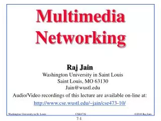
Example Caller jim@umass.edu with places a call to keith@upenn.edu(1) Jim sends INVITEmessage to umass SIPproxy. (2) Proxy forwardsrequest to upenn registrar server. (3) upenn server returnsredirect response,indicating that it should try keith@eurecom.fr (4) umass proxy sends INVITE to eurecom registrar. (5) eurecom registrar forwards INVITE to 197.87.54.21, which is running keith’s SIP client. (6-8) SIP response sent back (9) media sent directly between clients. Note: also a SIP ack message, which is not shown. 7: Multimedia Networking
H.323 is another signaling protocol for real-time, interactive H.323 is a complete, vertically integrated suite of protocols for multimedia conferencing: signaling, registration, admission control, transport, codecs SIP is a single component. Works with RTP, but does not mandate it. Can be combined with other protocols, services H.323 comes from the ITU (telephony) SIP comes from IETF: Borrows much of its concepts from HTTP SIP has Web flavor, whereas H.323 has telephony flavor. SIP uses the KISS principle: Keep it simple stupid Comparison with H.323 7: Multimedia Networking
7.1 multimedia networking applications 7.2 streaming stored audio and video 7.3 making the best out of best effort service 7.4 protocols for real-time interactive applications RTP, RTCP, SIP 7.5 providing multiple classes of service 7.6 providing QoS guarantees Chapter 7 outline 7: Multimedia Networking
Providing Multiple Classes of Service • thus far: making the best of best effort service • one-size fits all service model • alternative: multiple classes of service • partition traffic into classes • network treats different classes of traffic differently (analogy: VIP service vs regular service) • granularity: differential service among multiple classes, not among individual connections • history: ToS bits 0111 7: Multimedia Networking
Multiple classes of service: scenario H3 H1 R1 R2 H4 1.5 Mbps link R1 output interface queue H2 7: Multimedia Networking
R1 R2 Scenario 1: mixed FTP and audio • Example: 1Mbps IP phone, FTP share 1.5 Mbps link. • bursts of FTP can congest router, cause audio loss • want to give priority to audio over FTP Principle 1 packet marking needed for router to distinguish between different classes; and new router policy to treat packets accordingly 7: Multimedia Networking
R1 R2 Principles for QOS Guarantees (more) • what if applications misbehave (audio sends higher than declared rate) • policing: force source adherence to bandwidth allocations • marking and policing at network edge: • similar to ATM UNI (User Network Interface) 1 Mbps phone 1.5 Mbps link packet marking and policing Principle 2 provide protection (isolation) for one class from others 7: Multimedia Networking
Principles for QOS Guarantees (more) • Allocating fixed (non-sharable) bandwidth to flow: inefficient use of bandwidth if flows doesn’t use its allocation 1 Mbps logical link 1 Mbps phone R1 R2 1.5 Mbps link 0.5 Mbps logical link Principle 3 While providing isolation, it is desirable to use resources as efficiently as possible 7: Multimedia Networking
Scheduling And Policing Mechanisms • scheduling: choose next packet to send on link • FIFO (first in first out) scheduling: send in order of arrival to queue • real-world example? • discard policy: if packet arrives to full queue: who to discard? • Tail drop: drop arriving packet • priority: drop/remove on priority basis • random: drop/remove randomly 7: Multimedia Networking
Scheduling Policies: more Priority scheduling: transmit highest priority queued packet • multiple classes, with different priorities • class may depend on marking or other header info, e.g. IP source/dest, port numbers, etc.. • Real world example? 7: Multimedia Networking
Scheduling Policies: still more round robin scheduling: • multiple classes • cyclically scan class queues, serving one from each class (if available) • real world example? 7: Multimedia Networking