Download
1 / 1
10 likes | 135 Views
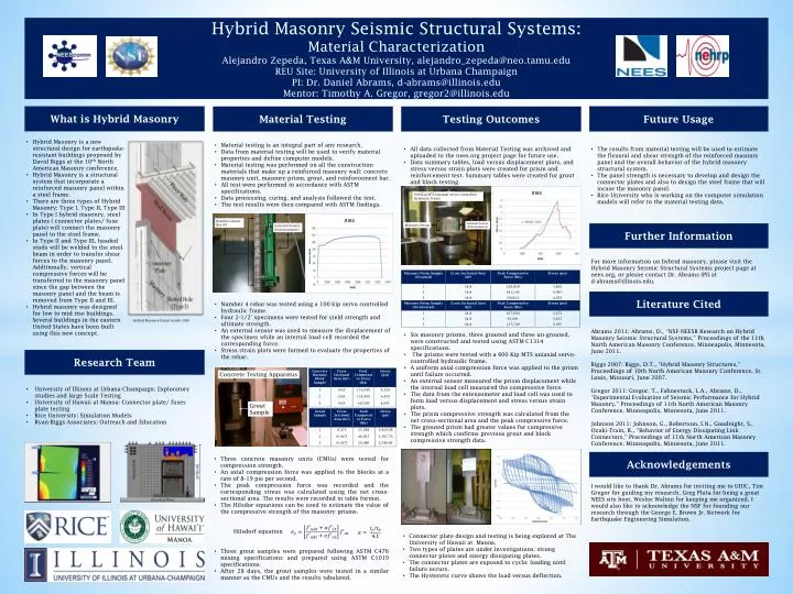
Hybrid Masonry Seismic Structural Systems: Material Characterization Alejandro Zepeda, Texas A&M University, alejandro_zepeda@neo.tamu.edu REU Site: University of Illinois at Urbana Champaign PI: Dr. Daniel Abrams, d-abrams@illinois.edu Mentor: Timothy A. Gregor , gregor2@illinois.edu.

E N D
Hybrid Masonry Seismic Structural Systems: Material Characterization Alejandro Zepeda, Texas A&M University, alejandro_zepeda@neo.tamu.edu REU Site: University of Illinois at Urbana Champaign PI: Dr. Daniel Abrams, d-abrams@illinois.edu Mentor: Timothy A. Gregor, gregor2@illinois.edu Future Usage What is Hybrid Masonry Material Testing Testing Outcomes • Hybrid Masonry is a new structural design for earthquake-resistant buildings proposed by David Biggs at the 10th North American Masonry conference. • Hybrid Masonry is a structural system that incorporate a reinforced masonry panel within a steel frame. • There are three types of Hybrid Masonry: Type I, Type II, Type III • In Type I hybrid masonry, steel plates ( connector plates/ fuse plate) will connect the masonry panel to the steel frame. • In Type II and Type III, headed studs will be welded to the steel beam in order to transfer shear forces to the masonry panel. Additionally, vertical compressive forces will be transferred to the masonry panel since the gap between the masonry panel and the beam is removed from Type II and III. • Hybrid masonry was designed for low to mid rise buildings. Several buildings in the eastern United States have been built using this new concept. • Material testing is an integral part of any research. • Data from material testing will be used to verify material properties and define computer models. • Material testing was performed on all the construction materials that make up a reinforced masonry wall: concrete masonry unit, masonry prism, grout, and reinforcement bar. • All test were performed in accordance with ASTM specifications. • Data processing, curing, and analysis followed the test. • The test results were then compared with ASTM findings. • All data collected from Material Testing was archived and uploaded to the nees.org project page for future use. • Data summary tables, load versus displacement plots, and stress versus strain plots were created for prism and reinforcement test. Summary tables were created for grout and block testing. • The results from material testing will be used to estimate the flexural and shear strength of the reinforced masonry panel and the overall behavior of the hybrid masonry structural system. • The panel strength is necessary to develop and design the connector plates and also to design the steel frame that will incase the masonry panel. • Rice University who is working on the computer simulation models will refer to the material testing data. 600 Kip MTS uniaxial servo-controlled hydraulic frame Reinforcement Bar #4 External Sensor (Extensometer) Masonry Prism External Sensor (Extensometer) Further Information For more information on hybrid masonry, please visit the Hybrid Masonry Seismic Structural Systems project page at nees.org, or please contact Dr. Abrams (PI) at d-abrams@illinois.edu. Literature Cited • Number 4 rebar was tested using a 100 kip servo controlled hydraulic frame. • Four 2-1/2’ specimens were tested for yield strength and ultimate strength. • An external sensor was used to measure the displacement of the specimen while an internal load cell recorded the corresponding force. • Stress strain plots were formed to evaluate the properties of the rebar. Hybrid Masonry Detail (credit: IMI) Abrams 2011: Abrams, D., “NSF-NEESR Research on Hybrid Masonry Seismic Structural Systems,” Proceedings of the 11th North American Masonry Conference, Minneapolis, Minnesota, June 2011. Biggs 2007: Biggs, D.T., “Hybrid Masonry Structures,” Proceedings of 10th North American Masonry Conference, St. Louis, Missouri, June 2007. Gregor 2011: Gregor, T., Fahnestock, L.A., Abrams, D., “Experimental Evaluation of Seismic Performance for Hybrid Masonry,” Proceedings of 11th North American Masonry Conference, Minneapolis, Minnesota, June 2011. Johnson 2011: Johnson, G., Robertson, I.N., Goodnight, S., Ozaki-Train, R., “Behavior of Energy Dissipating Link Connectors,” Proceedings of 11th North American Masonry Conference, Minneapolis, Minnesota, June 2011. • Six masonry prisms, three grouted and three un-grouted, were constructed and tested using ASTM C1314 specifications. • The prisms were tested with a 600 Kip MTS uniaxial servo-controlled hydraulic frame. • A uniform axial compression force was applied to the prism until failure occurred. • An external sensor measured the prism displacement while the internal load cell measured the compressive force. • The data from the extensometer and load cell was used to form load versus displacement and stress versus strain plots. • The prism compressive strength was calculated from the net cross-sectional area and the peak compressive force. • The grouted prism had greater values for compressive strength which confirms previous grout and block compressive strength data. Research Team Concrete Testing Apparatus • University of Illinois at Urbana-Champaign: Exploratory studies and large Scale Testing • University of Hawaii at Manoa: Connector plate/ fuses plate testing • Rice University: Simulation Models • Ryan-Biggs Associates: Outreach and Education Grout Sample Acknowledgements • Three concrete masonry units (CMUs) were tested for compression strength. • An axial compression force was applied to the blocks at a rate of 8-19 psi per second. • The peak compression force was recorded and the corresponding stress was calculated using the net cross-sectional area. The results were recorded in table format. • The Hilsdor equations can be used to estimate the value of the compressive strength of the masonry prisms. • Hilsdorf equation • Three grout samples were prepared following ASTM C476 mixing specifications and prepared using ASTM C1019 specifications. • After 28 days, the grout samples were tested in a similar manner as the CMUs and the results tabulated. I would like to thank Dr. Abrams for inviting me to UIUC, Tim Gregor for guiding my research, Greg Pluta for being a great NEES site host, Weslee Walton for keeping me organized. I would also like to acknowledge the NSF for founding our research through the George E. Brown Jr. Network for Earthquake Engineering Simulation. • Connector plate design and testing is being explored at The University of Hawaii at Manoa. • Two types of plates are under investigations: strong connector plates and energy dissipating plates. • The connector plates are exposed to cyclic loading until failure occurs. • The Hysteretic curve shows the load versus deflection.