Download
1 / 15
150 likes | 282 Views
Development and validation of a capability for wide-swath storm observations of ocean surface wind speed . Timothy L. Miller 1 ( tim.miller@nasa.gov ), M. W. James 1 , W. L. Jones 2 , C. S. Ruf 3 , E. W. Uhlhorn 4 , C. D. Buckley 5 , S. Biswas 2 , G. Shah 2 , and R. E. Hood 6

E N D
Development and validation of a capability for wide-swath storm observations of ocean surface wind speed Timothy L. Miller1 (tim.miller@nasa.gov), M. W. James1, W. L. Jones2, C. S. Ruf3, E. W. Uhlhorn4, C. D. Buckley5, S. Biswas2, G. Shah2, and R. E. Hood6 1NASA Marshall Space Flight Center, Huntsville, AL 2University of Central Florida 3University of Michigan 4NOAA/AOML/HRD 5Universities Space Research Association 6NOAA/UAS Program
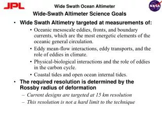
Hurricane Imaging Radiometer (HIRAD) • Passive microwave (C-band, 4 – 6.6 GHz) radiometer to infer wind speed over ocean surface • HIRAD’s unique contribution: Swath measurement of rain rate and hurricane-strength winds, even through heavy rain • Wind speed ~10 – 85 m/s • Rain rate ~ 5 – 100 mm/hr • Operations: Improveddefinition of maximum wind speed and vortex structure • Science hypothesis: Understanding of TC processes and short-term forecasts of intensity and structure will be improved by assimilation of HIRAD data
HIRAD physical principles • Emissivity of ocean surface is increased by the presence of sea foam generated by wind • Brightness temperature (Tb) measured by radiometer affected by: • Wind speed over the ocean surface • Rainwater column • Sea surface temperature and salinity • Earth incidence angle (EIA) – for H-pol, Tb drops off away from nadir • Weaker effects: Water vapor, cloud water, atmosphere temperature • Note: SFMR (Stepped Frequency Microwave Radiometer) uses similar frequencies, makes same measurement, but only at nadir • Flies operationally on NOAA and USAF aircraft • Wind speed relationship to Tb has been well validated • HIRAD makes cross-track scan using no moving parts • Synthetic thinned array radiometer (STAR) technology • Cross-track resolution ~2 km at nadir, ~6 km at 60o
Forward Model - RTM • Atmospheric Tap has three components: upwelling radiance (TUP), reflected down-welling radiance (Trefl) & surface emission (Tb)
Cross-correlation of signals from 10 linear antennae to produce cross-track resolution • Synthetic Thinned Array Radiometer (STAR) approach • HIRAD’s 10 linear antenna elements (oriented along-track) each observe a “fan beam” of radiation with fields of view which are narrow along-track, wide cross-track • Correlating amplitude + phase observations from pairs of antenna elements (interferometric analysis) produces cross-track Fourier components, which are combined to resolve cross-track brightness temperatures Receiver cards (10 + 1 used only for alignment in chamber), coaligned with linear antennae
HIRAD Calibration Procedure • Calibration measurements required: • Compact rangeanechoic chamber measurements with known emissions source, including both cross-track and along-track scans to fully characterize the antenna • Ground-based open sky and blackbody absorber measurements, including those with the antenna elements partially covered with a blackbody (BB) absorber, and partially open to the sky • Open, calm (or known wind), rain-free observations of the sea surface (with known SST, salinity) from aircraft. This will generally be done on each flight. • Calibration procedure: • Calibrate internal noise diode (warm and cold references) TBs and antenna/radome insertion loss using ground sky calplus BB absorber data. • Individually calibrate each of ten receivers (viewed as ten individual real aperture radiometers with fan beam antennas) using open water and BB absorber data plus modeled fan beam TB. • Calibrate all visibility (cross-correlation) data in anechoic chamber to generate interference patterns. • Derive pseudo-inverse of interference pattern “G-matrix”. This is the image reconstruction algorithm. • Perform antenna pattern correction to individual pixels in TB image (corrects for sidelobe contributions to TB) using open water and BB absorber data plus modeled TB in cross-track field of view vs. swath position.
First HIRAD flights: GRIP NASA Aircraft: • Global Hawk – Unmanned Aerial System based at Dryden Flight Facility, California • Instruments: Lightning Instrument Package (LIP), High-Altitude Imaging Wind and Rain Airborne Profiler (HIWRAP), and High Altitude MMIC Sounding Radiometer (HAMSR) • DC-8 – Based in Fort Lauderdale • Dropsondes, LASE, DAWN, APR-2, MMS, CAPS, CSI, PIP • WB-57 – Based in Houston, Tampa • Hurricane Imaging Radiometer (HIRAD)
Hurricane Earl Best Track HIRAD flight
Hurricane Earl Max Wind Speed HIRAD flight
HIRAD TB Images at 4.0, 5.0 and 6.6 GHzalong Northbound Earl Overpass Preliminary data 4.0 GHz 5.0 GHz 6.6 GHz UCF
SFMR passes over HIRAD swathStorm-centric coordinate system SFMR SFMR HIRAD and SFMR should match at HIRAD’s nadir point UCF
HIRAD/SFMR West Leg Overpass HIRAD Tb@ 4GHz Model Tb@ 5GHz HIRAD Tb@ 5GHz Model Tb@ 4GHz SFMR Wind +50 (m/s) SFMR Rain +50 (mm/hr) SFMR Flt Dir stop start “Model” data are Tb’s computed from SFMR wind & rain fields UCF
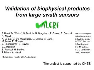
Karl Best Track HIRAD flights
Hurricane Karl Max Wind Speeds HIRAD flight HIRAD flights
Summary • The WB-57, with HIRAD aboard, flew once over Earl, 3 times over Karl during GRIP • Preliminary data analysis of the Earl case indicates excellent performance and comparison with SFMR • Currently developing data processing methodology to eliminate radio frequency interference (RFI) and to maintain calibration in all channels and sub-bands • Targeting release of Tb and wind/rain data in 2months • We hope in the future to develop HIRAD II, a fully polarimetricsystem that will detect wind direction • This technology has potential for space flight as a complement to scatterometers, lidars, and higher-frequency radiometers