Download
1 / 12
120 likes | 235 Views
Cinema Stein Interface FPGA (CSI) [Part II] Karthik Lakshmanan CINEMA - EE Team Space Sciences Laboratory University of California, Berkeley. Cinema Stein Interface FPGA - Agenda. AGENDA Overview Block Diagrams Requirements CSI Components Development Plan. Overview (1/2).

E N D
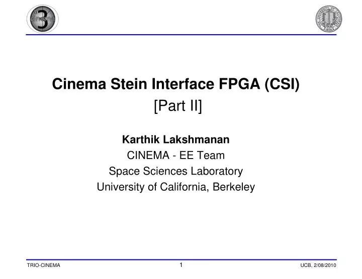
Cinema Stein Interface FPGA (CSI) • [Part II] • Karthik Lakshmanan • CINEMA - EE Team • Space Sciences Laboratory • University of California, Berkeley
Cinema Stein Interface FPGA - Agenda • AGENDA • Overview • Block Diagrams • Requirements • CSI Components • Development Plan
Overview (1/2) CSI is an Actel FPGA that resides in the STEIN electronics. Overall Context
Overview (2/2) Functional Description of CSI
CSI Components (1) • Cinema STEIN Interface FPGA Modules • FIXED DAC CONTROL • Handles all the LLD Threshold DAC values. • 6 DACS onboard • Inputs: SYNCH REGS_CMDPARMS • Registers: Fixed DAC Values(4) • Outputs: FDDAC: (CK, LD, CLR, DAT) Load DACs with updated voltage value.
ENABLE SWEEP SYNCH & ACCUMINT IDLE SYNCH DONE RESET ACCUMINT DONE LD DAC RD LUT DONE CSI Components (2) • Cinema STEIN Interface FPGA Modules • SWEEP DAC CONTROL • Controls 2 Sweep DACs which increment the detector voltage periodically. • It also periodically (once/second) loads two fixed DACs (BIAS and TestPulser). 128 steps/second => 32 steps/sweep and 4 sweeps/second. Lookup table based => reconfigurable Inputs ACCUMINT:. At every rising edge the SWEEP DAC voltage is updated from the LUT. CYCCOUNTS: CMDPARMS SRAMDATIN: Next voltage value read from LUT. Outputs SWDAC: (CK, LD, CLR, DAT) Load DACs with updated voltage value.
CSI Components (3) • LUT MEMORY • It stores the voltage pattern that the Sweep DAC has to follow. • 512 bytes of memory (out of 4.25kB available) • Loaded by REGS module • Read by SWEEP DAC module • Inputs: • SRAMDATIN(15:0) Input to memory. This is used when the table is loaded. • REGS_ADR Address Input from REGS module • SDAC_ADR Address Input from SDAC module • REGS_WR: Write to LUTM • SDAC_RD: Read from LUTM • ENBSWEEP: State of Sweep Subsystem (LUT Write-protected when Sweep is Active) • Outputs: • SRAMDATOUT(15:0): Voltage data read from table
CSI Components (4) • REGS (Command Interface) • Handles interfacing with off-board systems via CDI (Command Data Interface) • Interface bit rate = 8.4MHz, Data rate = 4Mbps (includes CDI Protocol) • Stores all command parameters. Commands become active at the 1 second tick after they were set. • Inputs • CMDCLK: Command Clock. Possibly the same as SCLK. The target frequency is 8.34MHz. • CMDDAT: Command Data • Outputs • REGS_CMDPARAMS: Command Parameters. These include all Register data. • Parity and Framing Errors are detected, and commands discarded if an error is present. No feedback is given regarding error-detection or command rejection. * A detailed description of this interface can be found in pages 10-11 of Reference 3 (MAVEN PFDPU to Instrument ICD).
CSI Components (5) • CDI (Command Data Interface) * • Falling Clock Edge to prevent conflict between CMD and CLK signals • System synchronises using Start/Stop bits • The parity is odd and includes the 24 command bits but not the start bit • Command Format is as shown below: Serial Command Timing * A more detailed description of this interface can be found in pages 10-11 of Reference 3 (MAVEN PFDPU to Instrument ICD).
Development Plans • Development • Specification Revision A just released • FPGA coding language : VHDL • Coding of modules to begin shortly. • Testing • All modules will be unit tested in VHDL