Download
1 / 33
330 likes | 428 Views
IE 447 COMPUTER INTEGRATED MANUFACTURING. CHAPTER 3 NUMERICAL CONTROL. Prepared by Hamed. A Definition:.

E N D
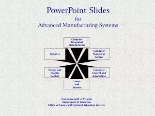
IE 447 COMPUTER INTEGRATED MANUFACTURING CHAPTER 3 NUMERICAL CONTROL Prepared by Hamed
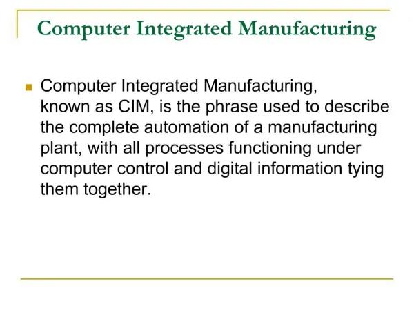
A Definition: Numerical Controlis a system in which actions are controlled by the direct insertion of numerical data at some point. The system must automatically interpret at least some portion of the data
NUMERICAL DATA (NC CODE) NUMERICAL CONTROLLER MANUFACTURING OPERATOR Drive Control PROCESSED PART MACHINE UNIT
Types of Numerical Control • Conventional Numerical Control (NC) • Direct Numerical Control (DNC) • Computer Numerical Control (CNC)
Conventional Numerical Control (NC) Data is sent to the machine tool by means of punch cards or tapes. The reader at the machine performs no calculations or interpolations.
Direct Numeric Control (DNC) Is a method where a single computer controls many numerical control machine tools. These machine tools may or may not be of a similar nature
Computer Numerical Control (CNC) The idea of computer numerical control is to position a computer right at the machine tool. Most, if not all machine tools that are numericaly controlled are CNC machine tools.
Advantages • Reduces time for delivery of part Reduces scrap rate of material • Reduces tooling costs • Reduces layout time • Increases machine and tool life • Reduces storage problems • Less setup time • Reduces actual machining time Allows rapid design changes in part Less jigs and fixtures are needed
NC Programming Fundamentals or how to put the “GO” in your G-codes
NC Part Programming • Linear tool motion (Milling) relative to the part
Example: A Milling Operation SPINDLE STOP ! NC CODE (Word Address Format) N50 G00 X15 Y12.5 Z0 N55 M03 N60 G01 Z-2.5 F500 M08 N65 G01 X50 N70 G01 Y45 N75 G01 X15 N80 G01 Y12.5 N85 G00 Z0 M09 N90 G79 M04 SPINDLE STARTED ! Z Y X (0,0,0)
Basics of NC Part Programming • it is always assumed that thetool moves relative to the work pieceno matter what the real situation is. • The position of the tool is described by using a Cartesian coordinate system. • If (0,0,0) position can be described by the operator, then it is called floating zero.
Preparatory Functions (G Codes) • Tool motion • Rapid traverse G00 • Positioning command • Moves the tool at a rapid feed rate to a specific XYZ coordinate • Takes the shortest route to reach the specified point • Format • G00 Xx Yy Zz G-codes
Linear Interpolation • Moves the tool from its current position to a specific XYZ coordinate at a specified feed rate • Format • G01 Xx Yy Zz ff G-codes
Linear Interpolation G-codes
Circular Interpolations • Moves a tool around a circular arc to a specific XYZ coordinate • Requires 5 pieces of information • Plane selection • Arc start point • Rotation direction • Arc end point • Arc center or arc radius G-codes
Circular Interpolations • G02 circular interpolation clockwise around an arc G03 circular interpolation counter clockwise around an arc G-codes
How You Tell Directions • The direction for G02 can be determined by rotating from the positive axes towards the negative axes. The direction for a G03 is exactly opposite G-codes
Still Going in Circles • basic methods • Radius method • (G02,G03) Xx Yy Rr Ff (on the XY plane) G-codes
Radius Method • Requires two entry parameters in the command the XYZ end point of the arc and the radius R • G02/G03 Xx Yy Zz Rr G-codes
G90 M3 S2000 ; G90 -absolute coordinate ; M3 - spindle ON ; S - RPM G0 X0 Y0 Z10 ;G0- rapid movement X10 Y5 Z2 G1 Z-2 F100 ;G1- linear movement ;F- feed X80 F200 X10 Y40 Y5 x80 Y40 x45 y45 x10 y40 x80 x80 y5 g0 z10 x0y0 M30 ; Spindle off X45 y45 X80 y40 X5 y40 X80 y10 X5 y10 G-codes
Homework #1 - Due date: March 10th Z=-2 Tool Diameter = 0.5 mm
Spindle On/Off Vice Open/Close E-stop