Download

1 / 27
270 likes | 389 Views
High Definition Manufacturing Cell Model. Wayne Wakeland Leupold & Stevens, Inc. ProModel Solutions Conference 2K2. Model Summary. Four CNC turning centers Plus several smaller pieces of equipment for deburring and finishing Purpose was to study: Capacity staffing requirements

E N D
High Definition Manufacturing Cell Model Wayne WakelandLeupold & Stevens, Inc. ProModel Solutions Conference 2K2
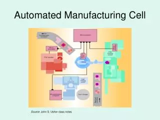
Model Summary • Four CNC turning centers • Plus several smaller pieces of equipment for deburring and finishing • Purpose was to study: • Capacity • staffing requirements • alternative equipment configurations
Model Level of Detail • Simulates the manufacture of 20 different parts • From 8 different sizes of bar stocks/extrusions • Each part has a unique routing through the cell • Some parts require extra deburring or finishing steps • Others do not
Preview of Results • One possible finishing process shown to be a bottleneck regardless of staffing levels • Tumbling followed by bead blast • This further motivated the search for alternative processes • An alternative process was found • The model showed it would not be a bottleneck • The model also showed that three operators could run the cell • Contrary to expectations of process engineer • Later validated in actual operation
Leupold & Stevens • Leading manufacturer of high quality riflescopes • Used by hunters and competitive shooters • Founded in 1907 • Began producing current line of products in 1947 • Currently exploring Lean manufacturing • After decades of using traditional batch processing • where parts are manufactured and finished in large batches • and stored in a stockroom before being issued to final assembly work orders
A New Product, the CQT, was being Developed • Became a demonstration product for Lean manufacturing • Substantial investment • Unique metal parts to be built on a daily basis… • In response to the immediate assembly needs • After fabrication in the CNC turning center, parts also require additional operations • To achieve the desired surface finish • Some of this processing is done within the cell
Potential Process Bottleneck • After fabrication and partial finishing, parts then go to a subcontractor • Located 17 miles away • Who “anodizes” the parts • To make the aluminum black and tougher • Two to three days later, the parts return • They are built into finished products within another two or three days
Throughput Goal • One week • From barstock to finished product • Very aggressive • Since historical throughput times range from 6-10 weeks
ProModel Model • Would it be feasible to build one day’s worth of parts every day? • By setting up a highly efficient “rotation” through the parts • There was concern about the finishing process for the external parts • Called “tumbling” • Would this prove to be a major bottleneck?
Modeling Challenges A • To write a substantial subroutine • That simulates the actual cutting of parts from raw material • loading another bar stock when needed • changing to the next part number once the daily quantity is completed • determining whether or not the next part requires a material change • etc.
Modeling Challenges B • To enhance the processing logic • So that the model can run through the parts rotation forwards or backwards • as is done in the real world • to avoid a part changeover at the start of each rotation • To correctly specify the priority logic • To indicate which tasks are done by each resource
Additional model features • Realistic animation • Not just for the operators as they carry out the various tasks • But also for the trays of parts as they are processed • And accumulate, prior to going to the subcontractor • Spreadsheet data links • For process cycle times, setup times, and material consumption amounts • To allow for the possibility of live linkages to the process data stored in the company’s MRP system
IF OWNEDRESOURCE() < 1 THEN GET RES_G200 OR RES_Flex IF V_NEWPN = 1 THEN //need to do changeover { WAIT ARR_G200ChgOvrTimes[V_PN + V_Offset] V_G200ChgOvrTime = V_G200ChgOvrTime + ARR_G200ChgOvrTimes[V_PN+V_Offset] A_Length = A_Length - ARR_G200SetupPartsPerChg[V_PN] * ARR_G200FTPerPart[V_PN] V_NewPN = 0 } ELSE WAIT M_BarChgTime IF V_PN = 10 THEN SEND 1 ENT_PSExtrusion TO LOC_BarPrepPSR FREE ALL startofloop: IF V_QtyBuilt < M_KANBANQty THEN { IF A_Length < M_MinBarLength + ARR_G200FTPerPart[V_PN] THEN { ROUTE 1 RETURN
} ELSE SUB_G200MakePart() } ELSE { V_PN = V_PN + V_Dir // get ready to make next part V_QtyBuilt = 0 IF V_PN = 0 THEN GOTO done IF V_PN > 1 THEN IF ARR_G200LastPart[V_PN - 1] = 1 THEN GOTO done IF ARR_G200NewMtl[V_PN + V_Offset] = 1 THEN { V_NewPN = 1 V_Route = ARR_G200StartVRoute[V_PN] ROUTE 2 +V_Offset //need to do changeover; offset is added if going backwards RETURN } ELSE
{ V_Route = V_Route + V_Dir // increment or decrement which route to take IF A_Length < M_MinBarLength + ARR_G200SetupPartsPerChg[V_PN] * ARR_G200FTPerPart[V_PN] THEN { V_NewPN = 0 //bar is not long enough to setup new part, need to get another bar ROUTE 1 RETURN } ELSE { GET RES_G200 OR RES_Flex //bar is long enough to do changeover WAIT ARR_G200ChgOvrTimes[V_PN + V_Offset] V_G200ChgOvrTime = V_G200ChgOvrTime + ARR_G200ChgOvrTimes[V_PN+V_Offset] A_Length = A_Length - ARR_G200SetupPartsPerChg[V_PN] * ARR_G200FTPerPart[V_PN] FREE ALL SUB_G200MakePart()
} } } GOTO startofloop done: //should get here only if done with a day's schedule V_G200_On = 0 V_G200_Done = CLOCK(HR) WAIT UNTIL V_G200_On = 1 V_DIR = V_Dir * (-1) V_PN = V_PN + V_Dir IF V_Offset = 0 THEN V_Offset = 1 ELSE V_Offset = 0 V_NewPN = 0 WAIT 1 // so as to not grab worker before they can unload the last handful GOTO startofloop
Model Validation • Modeler and process engineer carefully watched the animation to assure that • Each part is correctly routed • Operators perform the work in the correct sequence • Variables included to allow collection of data needed for validation • Many potential problems identified & corrected • E.g., with the resource/priority specifications in the operation/routing logic
Initial Results: Tumbling Not Good • Modeling the tumbler was a challenge • It contained four cylinders, but only one door • The cylinders rotated, with one of them being at the door position at any given time • Further, the media in the tumbler had to be washed after every other tumbling run • The model clearly showed that this would be a major bottleneck • And, further, that the problem could not be resolved through optimal operator behavior • The process was abandoned.
Enter “Shot Peening” • A different finishing process, • Identified by the Manufacturing Engineer • Much easier to model this process • Was quickly shown to be vastly superior • The equipment was ordered • The process has proven not to be a bottleneck operation
Staffing Analysis Results • Three operators should be able run the cell effectively • Assuming that the part changeovers could be done in the prescribed time • Operators would be kept quite busy, however • perhaps busier than their counterparts in the rest of the factory • Four operators were hired • To be on the safe side • During subsequent months, the production cell often had to run with only three operators • They were able to do so quite effectively
Was Daily Part Rotation Feasible? • The model clearly said No • This same conclusion was reached using spreadsheet analysis • But seeing it in the model was more compelling • It also showed that a 2-day rotation would work • The rotation could be accomplished by running two days worth of parts at a time • The process engineer knew that this was theoretically possible • But seeing the model results increased his confidence that it could actually be done • Subsequent operations validated this result
Sample Model Results • Resource Utilization % • RES G300 68.52 • RES G200 52.54 • RES ABC 55.37 • RES Flex 84.73 • RES G300S 42.70
One Year Later • Model resurrected to evaluate a swing shift to increase capacity • Model had to be enhanced significantly • Because swing shift would have less operators • And would have different objectives • Management objective: explore alternative staffing and operating rules • How many operators would be needed? • Should all three primary machines be run at once? • Or, should only two machines be run at a time?
More Modeling Challenges • To update the priority logic to accommodate two shifts with different staffing levels • Different operators perform the tasks on swing shift compared to day shift • Thus, the resources used on day and swing had to be different • And, much of the operation and routing logic had to be modified • It was difficult to get the downtime logic to work correctly for Locations • Resource downtimes worked fine
More Model Validation • The addition of second shift logic required careful re-validation • To assure that parts continued to move realistically • The previous validation done for day shift logic was irrelevant and had to be repeated • Since totally different resources are used on the second shift
Second Shift Analysis Results • Two operators would need to run all three machines for a couple of hours • But would only need to run two machines for most of the shift. • One operator could almost, but not quite, run the cell by himself • With only slightly reduced output • Giving an indication of what could be done when one second shift operator is not available • Overall, the parts manufacturing cell would have some excess capacity