Download
1 / 28
280 likes | 539 Views
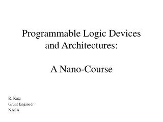
Programmable Logic Controllers PLC’s. Overview. Overview of Technology PLC Configuration and Selection Programming PLC’s. What is a PLC ?. PLC (Programmable Logic Controller)

E N D
Overview • Overview of Technology • PLC Configuration and Selection • Programming PLC’s
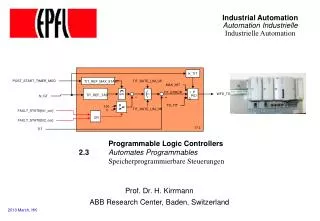
What is a PLC ? • PLC (Programmable Logic Controller) • A PLC works by looking at its inputs and depending on their state, and the user entered program, turns on/off outputs. • A PLC can be thought of as: Industrial Computers with specially designed architecture in both their central units (the PLC itself) and their interfacing circuitry to field devices (input / output connections to the real world).
Basic PLC Schema • CPU • Power Supply • Memory • Input Blocks • Output Blocks • Communications • Expansion Connections
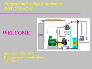
CPU Module • The Central Processing Unit (CPU) Module is the brain of the PLC. • Primary role to read inputs, execute the control program, update outputs. • The CPU consists of the arithmetic logic unit (ALU), timing/control circuitry, accumulator, scratch pad memory, program counter, address stack and instruction register. • A PLC works by continually scanning a program PLC Program SCAN
Memory • The memory includes pre-programmed ROM memory containing the PLC’s operating system, driver programs and application programs and the RAM memory. • PLC manufacturer offer various types of retentive memory to save user-programs and data while power is removed, so that the PLC can resume execution of the user-written control program as soon as power is restored.
I/O Modules • Input and output (I/O) modules connect the PLC to sensors and actuators. • Provide isolation for the low-voltage, low-current signals that the PLC uses internally from the higher-power electrical circuits required by most sensors and actuators. • Wide range of I/O modules available including: digital (logical) I/O modules and analog (continuous) I/O modules.
Inputs Modules • Inputs come from sensors that translate physical or chemical phenomena into electrical signals. • The simplest form of inputs are digital/discrete in AC/DC. • In smaller PLCs the inputs are normally built in and are specified when purchasing the PLC. • For larger PLCs the inputs are purchased as modules, or cards, with 8,16, 32, 64, 96 inputs of the same type on each card.
Inputs Modules The list below shows typical ranges for input voltages. 5 Vdc 12 Vdc 24 Vdc 48 Vdc 12 Vac 24 Vac 120 Vac 240 Vac
Outputs Modules • Output modules rarely supply any power, but instead act as switches. • External power supplies are connected to the output card and the card will switch the power on or off for each output. • A common choice when purchasing output cards is relays, transistors or triacs. • Relay are the most flexible output devices. They are capable of switching both AC and DC outputs. But, they are slower, cost more, and they will wear out after millions of cycles.
Relays • The most important consideration when selecting relays, or relay outputs on a PLC, is the rated current and voltage. • For transistor outputs or higher density output cards relay terminal blocks are available. • Advantage of individual standard replaceable relays
Outputs Typical output voltages are listed below, 5 Vdc 12 Vdc 24 Vdc 48 Vdc 24 Vac 120 Vac 240 Vac WARNING: Always check rated voltages and currents for PLCs and never exceed.
Analogue Cards • Typical Analogue Input signals are: • Flow sensors • Humidity sensors • Load Cells • Potentiometers • Pressure sensors • Temperature sensors • Vibration • Analogue Output signals control: • Analogue Valves • Actuators • Chart Resorders • Variable Speed Drives • Analogue Meters • Typical Analogue Signal Levels • 4-20mA • 1-5 Vdc • 0-10 Vdc • -10 – 10Vdc
Analogue Inputs/Outputs • Analogue input cards convert continuous signals via a A/D converter into discrete values for the PLC • Analogue output cards convert digital values in then PLC to continuous signals via a D/A converter. • Resolution can be important in choosing an applicable card • Example, for a temperature input of 0 to 100 degrees C • For 8 bit resolution the value in the PLC is 0 to 255 • For 12 bit resolution the value in the PLC is 0 to 4095 • For 12.5 bit resolution the value in the PLC is 0 to 6000 • For 13 bit resolution the value in the PLC is 0 to 8192 • For 16 bit resolution the value in the PLC is 0 to 32768
Special Modules • RF ID • Voice • Gas Flow Calculation • Weigh Cell • Hydraulic Servo • ASCII • Fuzzy Logic • Temperature Sensor • Temperature Control • Heat/Cool Control • Field Bus Cards • DeviceNet, Profibus etc • Lonworks, BACNet • Fast Response (Interrupt) • PID • Loop Controller • BASIC Cards • RS232 Comm’s • Modbus ASCII/RTU • Ethernet Comm’s • High Speed Counters • Position Control Cards • Per to Per Comm’s • Controller Link • DH+ • Modbus Plus
Available Instructions • Sequence • Input • Output • Control • Logic • Timer and Counters • Comparison • Range Comparison • Data Movement • Data Shift • Step / Step Next • Serial Communications • Text String Processing • File Manipulation • Increment/Decrement • Conversion • ASCII • Number Systems • Math • Floating Point Math • Statistics • Scaling • PID • PID with Auto tune • Clock / Date • Block Processing • IF,THEN,ELSE,LOOP Table Processing • LIFO, FIFO
PLC Configuration MINI RACK SHOE BOX MICRO
The Configuration of PLC • The configuration of PLC refers to the packaging of the components. • Typical configurations are listed below from largest to smallest. • Rack Type : A rack can often be as large as 18” by 30” by 10” • Mini: These are similar in function to PLC racks, but about the half size. Dedicated Backplanes can be used to support the cards OR DIN rail mountable with incorporated I/O bus in module. • Shoebox: A compact, all-in-one unit that has limited expansion capabilities. Lower cost and compactness make these ideal for small applications. DIN rail mountable. • Micro: These units can be as small as a deck of cards. They tend to have fixed quantities of I/O and limited abilities, but costs will be lowest. DIN rail mountable.
Sizing of PLC Micro PLCs: I/O up to 32 points Small PLC: I/O up to 128 points Medium PLC: I/O up to 1024 points Large PLC: I/O up to 4096 points Very Large: I/O up to 8192 points
Selecting a PLC • Criteria • Number of logical inputs and outputs • Memory • Number of special I/O modules • Expansion Capabilities • Scan Time • Communication • Software • Support • Dollars
Manufactures • OMRON • Allen Bradley • Schneider (Modicon, Telemecanique, Square D) • GE Fanuc • Siemens • Automation Direct (Koyo) • Toshiba • Mitsubishi • Hitachi • Keyence • Festo • Eberle • Texas Instruments • April MajorBrands
Programming PLC’s • Ladder Logic remains the most common technique for programming PLC’s