Download

1 / 31
320 likes | 519 Views
Computer-System Structures. General System Architecture and I/O. Input/Output Architecture. Computer-System Operation. I/O devices and the CPU can execute concurrently. Each device controller is in charge of a particular device type. Each device controller has a local buffer.

E N D
Computer-System Structures General System Architecture and I/O
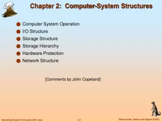
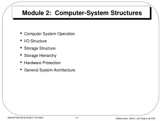
Computer-System Operation • I/O devices and the CPU can execute concurrently. • Each device controller is in charge of a particular device type. • Each device controller has a local buffer. • CPU moves data from/to main memory to/from local buffers • I/O is from the device to local buffer of controller. • Device controller informs CPU that it has finished its operation by causing an interrupt.
Interrupt Causes • Hardware: A device sends a signal through a hard-wired port to signal that it needs attention. • Software: A special instruction that generates an interrupt • Terminology: A trap is a software-generated interrupt caused either by an error or a user request (like a system call)
What Happens on an Interrupt? • Interrupt causes the HARDWARE to transfer control to the interrupt service routine (ISR) • Through the interrupt vector (usually), which contains the addresses of all the ISRs. • Interrupt architecture must save the address of the interrupted instruction. • Need an instruction like • “JALR” (from LC2K) • “bl” and “blr” (from PPC)
What Happens on an Interrupt? • Incoming interrupts are disabled while another interrupt is being processed to prevent a lost interrupt. • An operating system is interrupt driven. • That is how it gets/exerts control over the applications
Interrupt Handling • The operating system preserves the state of the CPU by storing registers and the program counter. • Determines which type of interrupt has occurred: • polling • vectored interrupt system • Separate segments of code determine what action should be taken for each type of interrupt
Synchronous I/O Structure • After I/O starts, control returns to user program only upon I/O completion. • Wait instruction idles the CPU until the next interrupt • Wait loop (contention for memory access). • At most one I/O request is outstanding at a time, no simultaneous I/O processing.
Asynchronous I/O Structure • After I/O starts, control returns to user program without waiting for I/O completion. • System call – request to the operating system to allow user to wait for I/O completion. • Device-status table contains entry for each I/O device indicating its type, address, and state. • Operating system indexes into I/O device table to determine device status and to modify table entry to include interrupt.
Two I/O Methods Asynchronous Synchronous
Direct Memory Access (DMA) • Used for high-speed I/O devices able to transmit information at close to memory speeds. • Device controller transfers blocks of data from buffer storage directly to main memory without CPU intervention. • Only one interrupt is generated per block, rather than the one interrupt per byte.
Storage Structure • Main memory • Only large storage media that the CPU can access directly. • Secondary storage • extension of main memory that provides large nonvolatile storage capacity.
Storage Structure • Magnetic disks • metal or glass platters covered with magnetic recording material • Disk surface is logically divided into tracks, which are subdivided into sectors. • The disk controller determines the logical interaction between the device and the computer.
Storage Hierarchy • Storage systems organized in hierarchy. • Speed • Cost • Volatility • Caching • copying information into a faster storage system • main memory can be viewed as a last cache for secondary storage.
Caching • Use of high-speed memory to hold recently-accessed data. • Requires a cache management policy. • Caching introduces another level in storage hierarchy. This requires data that is simultaneously stored in more than one level to be consistent.
Hardware Protection Dual-Mode Operation I/O Protection Memory Protection CPU Protection
Dual-Mode Operation • Shared system resources • OS must not allow an incorrect program to cause other programs to execute incorrectly. • Provide hardware support to differentiate between at least two modes of operations. 1. User mode – execution done on behalf of a user. 2. Monitor mode (also kernel mode or system mode) - execution done on behalf of operating system.
Dual-Mode Operation (Cont.) • Mode bit added to computer hardware to indicate the current mode: monitor (0) or user (1). • When an interrupt or fault occurs hardware switches to monitor mode. Interrupt/fault monitor user set user mode Privileged instructions can be issued only in monitor mode.
I/O Protection • All I/O instructions are privileged instructions. • User program must never gain control of the computer in kernel mode • (e.g., a user program that, as part of its execution, stores a new address in the interrupt vector).
Memory Protection (Segmentation) • Must provide memory protection at least for the interrupt vector and the interrupt service routines. • To have memory protection, add two registers that determine the range of legal addresses a program may access: • Base register – holds the smallest legal physical memory address. • Limit register – contains the size of the range • Memory outside the defined range is protected.
Hardware Protection • When in kernel mode, the OS has unrestricted access to both monitor and user’s memory. • The load instructions for the base and limit registers are privileged instructions.
CPU Protection • Timer • interrupts computer after specified period to ensure operating system maintains control. • is decremented every clock tick. • when timer reaches the value 0, an interrupt occurs. • Timer commonly used to implement time sharing. • Time also used to compute the current time. • Loading the timer is a privileged instruction.