Download
1 / 39
850 likes | 1.82k Views
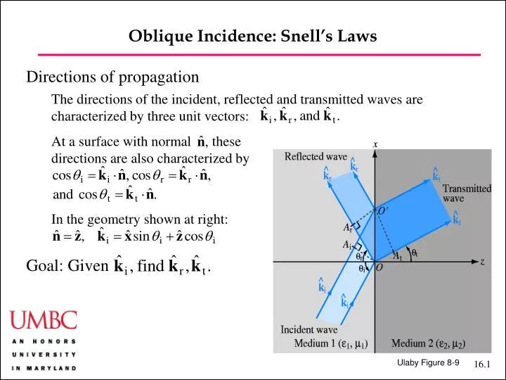
Oblique Incidence: Snell’s Laws. Directions of propagation The directions of the incident, reflected and transmitted waves are characterized by three unit vectors: At a surface with normal these directions are also characterized by In the geometry shown at right: Goal: Given.

E N D
Oblique Incidence: Snell’s Laws • Directions of propagation • The directions of the incident, reflected and transmitted waves are characterized by three unit vectors: • At a surface with normal thesedirections are also characterized by • In the geometry shown at right: • Goal: Given Ulaby Figure 8-9
Oblique Incidence: Snell’s Laws • Goal: Given • This problem is a waves problem, not an electromagnetics problem! • Maxwell’s equations are not needed to solve it • It was solved by Snell (and Descartes) 400 years ago! • The solution is the same for any wave at an interface • Key idea: The phase of all threewaves at every point on the interfacemust be the same!or position vector on the interface Ulaby Figure 8-9
Oblique Incidence: Snell’s Laws • Consequences: • All frequencies are the same:wt = wr = wi = w[We already used this consequence to equate • All wave vectors are in the same planeis on theinterface, so and all wave vectors are on theplane normal to A.[Hence, defining the anglesqi, qr, and qt is sufficient.] Ulaby Figure 8-9
Oblique Incidence: Snell’s Laws • Consequences: • Snell’s Law of Reflection:qr = qiWe have kr = ki = k1. In the geometry below, we also have kxr = kxi.It follows that kzr = –kzi. Since the angles are defined in oppositedirections, the equality follows. • Snell’s Law of RefractionWe haveWe also have The result follows aftersubstitution. Ulaby Figure 8-9
Oblique Incidence: Snell’s Laws • Consequences in Electromagnetics: • Snell’s laws in the following form apply to any waves: • Other forms of Snell’s Law of Refraction are useful in electromagnetism • Defining the index of refraction, • Snell’s Law of Refraction becomes * Note that the subscript r here refers to “relative,” not “reflected.”
Oblique Incidence: Snell’s Laws • Critical Angle: • When n1 < n2, we have qt < qi • When n1 > n2, we have qt > qi— as long as (n1/n2 )sinqi <1,which implies • The angle qc is referred to as thecritical angle. • When qi > qc, there is notransmitted wave. This effect is calledtotal internal reflection Ulaby Figure 8-10
Waves at Boundaries • What you see from the bottom of a pool: • A circle of visibility, surrounded by a silvery sheen • Objects near the edge of the pool appear suspended in air • Many similar phenomenaexist • A stick placed in water appears bent • Coins and other solid objects can also bend Air-water interface Magicians and con artists takeadvantage of this!
Waves at Boundaries Example: Cone of Visibility and Apparent Height in Water Question: The index of refraction of water is approximately n = 1.3 for visible light. You are looking up from the bottom of a pool. What is the angle that the cone of visibility makes with the surface normal? Suppose that the edge of the pool is 20 feet away and at the edge there is a pennant that is 5 feet above the ground. Ignoring distortion, how high does the pennant appear to be? Answer: The angle that the cone of visibility makes with the surface is just the critical angle. We have The angle that the light from the pennant makes with respect to the surface normal is given by It followsthat which corresponds to 48.3o. Neglecting distortion, we may assume that the distance from the water appears unchanged, and that it is given by So, the apparent height is given by 20.6cos(48.3o) = 14 ft. This angle is close to the critical angle, and there will be considerable distortion!
Fiber Optics • Waves are guided by total internal reflection! • An optical fiber consists of a cylinder of glass, called the fiber core, surrounded by a glass with a lower index of refraction, called the cladding. We write nc = cladding index and nf = fiber core index. • We must have • Relative to the incidence angle, we have Ulaby Figure 8.12
Fiber Optics • Waves are guided by total internal reflection! • From the condition , it follows that • where qa is the acceptance angle, inside of which the light is confined. • Not every angle can propagate! The allowed angles are quantized by the requirement of phase coherence. (Waves that arrive at the same point by different paths must have the same phase.) This requirement is the same in any waveguide!! Ulaby Figure 8.12
Fiber Optics • Two kinds of optical fibers [l = 1.0 – 1.3 mm] • Single-mode fibers: [diameter < 10 mm] Only one mode (actually two polarization modes) propagate. Used for long-distance communications • Dispersion is intra-modal (due to frequency spread; birefringence) • Dispersive scale lengths are hundreds of kilometers • Multi-mode fibers: [diameter ~ 100 mm] Many modes can propagate.Used for short-haul applications, e.g., 1- and 10-Gbs ethernet • Dispersion is inter-modal (due to different velocities of different modes) • Dispersive scale lengths are hundreds of meters Ulaby Figure 8.13
Fiber Optics • Modal Dispersion in Multi-mode fibers • Allowed spreading criterion: • Spreading occurs because all rays travel at a velocity up = c /nf, and rays at the edge of the acceptance cone must travel a longer distance to reach the same z-point along the fiber than do rays that go straight down the center. Hence, these rays arrive at a later time. [Other rays in the acceptance cone arrive in between these two extremes.] Ulaby Figure 8.13
Fiber Optics • Modal Dispersion in Multi-mode fibers • We have • We thus findwhere fp = data rate Ulaby Figure 8.13
Fiber Optics Data Rate in Optical Fibers: Ulaby Example 8-5 Question: A 1 km long optical fiber (in air) is made of a fiber core with an index of refraction of 1.52 and a cladding with an index of refraction of 1.49. Determine (a) the acceptance angle qa, and (b) the maximum data rate fp. Answer: For the acceptance angle, we have the equation which corresponds to qa = 0.305 rads = 17.5o. For the maximum data rate, we have * We lose two places of accuracy in the data rate because of the subtraction 1.52 – 1.49.
Tech Brief 15: Lasers Light Amplification by Stimulated Emission of Radiation Source of monochromatic, coherent, narrow beam light First laser built by Maiman in 1960. Basic Principles Atom can be modeled by a nucleus surrounded by a cloud of electrons at discrete energy levels. Adding energy can raise an electron to a higher energy level. Spontaneous emission happens when an electron moves to a lower state without external stimulus and emits a photon. Stimulated emission occurs when incident light (photons) induces an electron to decay and emit a photon of the same energy, wavelength and phase. Applications – too numerous to mention, but includes CD/DVD players, bar- code readers, eye surgery, etc.
Tech Brief 15: Lasers Lasing medium – solid, liquid, or gas. Electrons are pumped (electronically, optically, or otherwise) to higher states. Some atoms will spontaneously emit, which induces other atoms to emit photons at the same wavelength. Light then travels back and forth in the cavity, with some escaping and the rest stimulating more emission. Wavelength may be chosen by picking a suitable lasing medium with appropriate energy gaps.
Oblique Incidence: Reflection and Transmittance • Two special polarizations: TE and TM • With normal incidence: • Geometry is cylindrically symmetric • The polarizations are degenerate • any choice of the x- and y-axes is allowed • the polarization state is unchanged by reflection and refraction • With oblique incidence: • There are two special cases: (1) E surface; (2) H surface • The surface interaction breaks the degeneracy • these two cases have different coefficients of reflection and refraction • the polarization state of these two special cases is unchanged by reflection and refraction • the polarization state of any other caseis changed by reflection and refraction Example: Circular polarization becomes elliptical Ulaby Figure 8-14
Oblique Incidence: Reflection and Transmittance • Two special polarizations: TE and TM • This is a serious complication! • Definitions • Plane of incidence = plane defined by • We note: • Case (1): E surface • E is perpendicular to the plane of incidence • Case (2): H surface • E is parallel to the plane of incidence • More definitions: • Case (1): perpendicular polarizationor transverse electric polarization (TE) • Case (2): parallel polarization or transverse magnetic polarization (TM) Ulaby Figure 8-14
Oblique Incidence: Reflection and Transmittance • Method of analysis for arbitrary input • Decompose the input polarization into a sumof perpendicular and parallel polarizations • Separately determine the reflected and transmittedamplitudes for the two special polarizations • Sum the results to find the reflected and transmittedwaves • Finding the reflection and transmission coefficients • for the special polarizations is required to analyze • the reflection and transmission for any polarization! Ulaby Figure 8-14
Oblique Incidence: Reflection and Transmittance • Perpendicular Polarization • We take the x-z plane as our plane of incidence: Ulaby Figure 8.15
Oblique Incidence: Reflection and Transmittance • Perpendicular Polarization • Incident Wave: • with • Reflected Wave:
Oblique Incidence: Reflection and Transmittance • Perpendicular Polarization • Transmitted Wave: • with
Oblique Incidence: Reflection and Transmittance • Perpendicular Polarization • Boundary conditions: • — The tangential components of E and H must be continuous • These conditions become
Oblique Incidence: Reflection and Transmittance • Perpendicular Polarization: Boundary Conditions • From the phase-matching condition, we have: • These conditions imply Snell’s laws! • Our boundary conditions now become • where we made use of qr = qi
Oblique Incidence: Reflection and Transmittance • Perpendicular Polarization: Fresnel Coefficients • We conclude • We also have in a non-magnetic medium ( m1 = m2 = m0 ) • These are called the Fresnel coefficients for perpendicular polarization
Oblique Incidence: Reflection and Transmittance • Parallel Polarization • We proceed by analogy with the perpendicular case and find: • These are the Fresnel coefficients • for parallel polarization Ulaby Figure 8.16
Oblique Incidence: Reflection and Transmittance • Parallel Polarization • For non-magnetic materials, we have: Ulaby Figure 8.16
Oblique Incidence: Reflection and Transmittance • Brewster Angle, qB • At this incidence angle, G = 0, and all the energy is transmitted. • It is also called the polarizing angle, because it is not the same for the twopolarizations • Perpendicular polarization: • Condition: • We find • For non-magnetic materials, there is noperpendicular Brewster angle! Ulaby Figure 8.17
Oblique Incidence: Reflection and Transmittance • Brewster Angle, qB • Parallel polarization: • Condition: • We find • which in the case of non-magneticmaterials implies Ulaby Figure 8.17
Oblique Waves at Boundaries Example: Oblique Wave on a Soil Surface [Modified from Ulaby Example 8-6] Question: A right-circularly polarized wave radiated by a distant antenna is incident in air upon a soil surface at z = 0. The electric field is given by and the soil can be assumed to be a lossless dielectric with a permittivity of 4. (a) Verify that Ei corresponds to the field of a right-circularly polarized wave and determine (b) Find expressions for the electric field phasors in air and soil. What is the ellipticity of the transmitted wave?
Oblique Waves at Boundaries Example: Oblique Wave on a Soil Surface [Modified from Ulaby Example 8-6] Question: A right-circularly polarized wave radiated by a distant antenna is incident in air upon a soil surface at z = 0. The electric field is given by and the soil can be assumed to be a lossless dielectric with a permittivity of 4. (c) At what incident angle would the reflected polarization be linear?
Oblique Waves at Boundaries Example: Oblique Wave on a Soil SurfaceAnswer: (a)In order for Ei to correspond to an electromagnetic wave, we must have From the argument of the cosine and sine, we haveWe also have While not needed to answer this problem, we note that we also have To verify that Ei is right-circularly polarized, it is useful to change coordinate systems. We let which implies In this new coordinate system, our expression for the incident field becomes which corresponds to right-circular polarization.
Oblique Waves at Boundaries Example: Oblique Wave on a Soil SurfaceAnswer (continued): (b)From Snell’s laws, we havewhich impliesThe Fresnel coefficients are The initial electric field phasors are which implies and
Oblique Waves at Boundaries Example: Oblique Wave on a Soil SurfaceAnswer (continued): (b-continued)We haveand Explicitly, in the time domain, we have Making the transformation,we havecorresponds to a right-elliptically polarized wave, with (c) A linearly polarized wave will be reflected when the incident angle equals the Brewster angle for the parallel polarization. This angle is given by
Power Conservation • Reflectivity and Transmittivity • Consider an illuminated spot. We have for the average power densities • with the cross-sectional areas, • The average powers carried by the beams are Ulaby Figure 8.18
Power Conservation • Reflectivity and Transmittivity • We now define a reflectivity • and a transmittivity • Conservation of power implies: • Defining analogously, • we have
Tech Brief 16: Bar-Code Readers Bar codes Consist of parallel bars of certain widths encoding a binary sequence. Laser scanners can read the bar code and transfer the information to a computer. Basic Operation Laser focused a mirror rotation 6000 rpm, creating a fan beam. Beam direction changes constantly. One direction should include the bar code to be read. Light reflects off the white parts, but not the black parts, which is detected by the sensor and converted to an electrical signal. To eliminate interference, a glass filter is used to block ambient light.
Assignment • Reading: NONE! Prepare for final exam. • Problem Set 8: Some notes. • There are 6 problems. As always, YOU MUST SHOW YOUR WORK TO GET FULL CREDIT! • The problems are non-trivial; please get started early. • Please watch significant digits.