Download

1 / 150
1.92k likes | 4.69k Views
Behavior, Modeling and Design of Shear Wall-Frame Systems. Naveed Anwar. Asian Center for Engineering Computations and Software, ACECOMS, AIT. The Basic Issues. Modeling and analysis issues Transfer of loads to shear walls Modeling of shear walls in 2D Modeling of shear Walls in 3D

E N D
Behavior, Modeling and Design of Shear Wall-Frame Systems Naveed Anwar Asian Center for Engineering Computations and Software, ACECOMS, AIT
The Basic Issues • Modeling and analysis issues • Transfer of loads to shear walls • Modeling of shear walls in 2D • Modeling of shear Walls in 3D • Interaction of shear-walls with frames • Design and detaining issues • Determination of rebars for flexure • Determination of rebars for shear • Detailing of rebars near openings and corners • Design and detailing of connection between various commonest of cellular shear walls
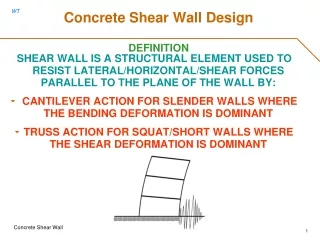
Shear Wall – Common Misconceptions • Due to misleading name “Shear Wall” • The dominant mode of failure is shear • Strength is controlled by shear • Designed is governed primarily by shear • Force distribution can be based on relative stiffness
Shear Wall or Frame Shear Wall or Frame ? Shear Wall Frame
Shear Wall and Frame Frame Behavior Shear Wall Behavior
Frame and Frame-Shear Wall A-1 A-2 A-3 B-4 B-1 B-2 B-3 B-4
Shear Wall and Frame Interaction • Frames Deform • Predominantly in a shear mode • Source of lateral resistance is the rigidity of beam-column/slab joints • Shear Wall Deform • Essentially in bending mode • Shear deformations are rarely significant • Only very low shear walls with H/W ratio <1 fail in shear • Behave mostly like a slender cantilever • Designed to resist the combined effect of axial, bending and shear
The Basic Behavior of Shear Walls, Frames and Shear Wall-Frames
Case Studies: Shear Wall–Frame Interaction For each 10, 20 and 30 story buildings Only Frame( Total 3 Cases ) Only Shear + Frame ( Total 3 Cases ) Only Shear Wall( Total 3 Cases ) Total 3x3 = 9 Cases
Case 1: Shear Wall–Frame Interaction D = 26.73 cm 10 Story Wall Wall Thickness = 15 cm
Case 2: Shear Wall–Frame Interaction 10 Story Frame D = 15.97 cm Beam Section = 60 cm x 30 cm Column Section = 50 cm x 50 cm
Case 3: Shear Wall–Frame Interaction 10 Story Wall and Frame D = 5.14 cm Wall Thickness = 15 cm Beam Section = 60 cm x 30 cm Column Section = 50 cm x 50 cm
Case 4: Shear Wall–Frame Interaction 20 Story Wall D = 158.18 cm Wall Thickness = 20 cm
Case 5: Shear Wall–Frame Interaction 20 Story Frame D = 27.35 cm Beam Section = 60 cm x 30 cm Column Section = 75 cm x 75 cm
Case 6: Shear Wall–Frame Interaction 20 Story Wall and Frame D = 12.66 cm Wall Thickness = 20 cm Beam Section = 60 cm x 30 cm Column Section = 75 cm x 75 cm
Case 7: Shear Wall–Frame Interaction 30 Story Wall D = 355.04 cm Wall Thickness = 30 cm
Case 8: Shear Wall–Frame Interaction D = 40.79 cm 30 Story Frame Beam Section = 60 cm x 30 cm Column Section = 100 cm x 100 cm
Case 9: Shear Wall–Frame Interaction 30 Story Wall and Frame D = 20.87 cm Wall Thickness = 30 cm Beam Section = 60 cm x 30 cm Column Section = 100 cm x 100 cm
Shear Wall–Frame Interaction Stiffness = Force / D • = Force / Stiffness For the cases considered here (30 story example): Force=200 Deflection = 40.79 Stiffness Frame = 200 / 40.79 = 04.90 Stiffness Wall = 200 / 355.04 = 00.56 Stiffness Frame + Wall = 200 / 12.66 = 15.79 Stiffness Frame +Stiffness Wall = 4.90 + 0.56 = 5.46 Stiffness Frame +Stiffness WallStiffness Frame + Wall
Change in Shear Wall Moments Shear Wall Moments for the Coupled System
Deflected Shape of Shear Wall-Frame Interactive System Khan-Sbarounis Curves
Comparison of Shears and Moments in the Core wall 4 Different Layouts for Same Function Requirements Type A Type B Type C Type D
Comparison of… : Type A Typical Floor Plan- Structure Type A
Comparison of… : Type B Typical Floor Plan- Structure Type B
Comparison of… : Type C Typical Floor Plan- Structure Type C
Comparison of… : Type D Typical Floor Plan- Structure Type D
Wall-Frame Interaction: Key Conclusions • The shear wall deform predominantly in bending mode • The common assumptions to neglect the frames in lateral load resistance can lead to grossly erroneous results • Consideration of shear wall-frame interaction leads to a more economic design • The shear walls should be designed to resist the combined effect of axial, bending and shear • Layout of the shear walls in plan in very important, both for vertical as well as gravity load
Modeling of Walls using 1D Elements Beam elements with rigid ends Simple beam elements H2 H1 t t L L Beam elements in “Truss Model” t x h L
Frame Model for Planer Walls • Specially Suitable when H/B is more than 5 • The shear wall is represented by a column of section “B x t” • The beam up to the edge of the wall is modeled as normal beam • The “column” is connected to beam by rigid zones or very large cross-section H t B Rigid Zones
Frame Models for Cellular Walls t • Difficult to extend the concept to Non-planer walls • Core Wall must be converted to “equivalent” column and appropriate “rigid” elements • Can be used in 2D analysis but more complicated for 3D analysis • After the core wall is converted to planer wall, the simplified procedure cab used for modeling H B 2t H t B
Modeling Walls using 2D Elements • Walls are subjected to in-plane deformations so 2D elements that have transnational DOF need to be used • A coarse mesh can be used to capture the overall stiffness and deformation of the wall • A fine mesh should be used to capture in-plane bending or curvature • General Shell Element or Membrane Elements can be used to model Shear Walls
Modeling Walls Using Membrane The Incomplete Membrane Element Nodes: 4 DOFs: 2 DOFs /Node Ux and Uy 2-Translation Dimension: 2 dimension element Shape: Regular / Irregular Properties: Modulus of Elasticity(E), Poisson ratio(v), Thickness( t ) This “Incomplete” Panel or Membrane Element does not connect with Beams completely and rotation DOF of beams and the ends are “Orphaned”
Modeling Walls using Shell Elements The Complete Membrane Element Nodes: 4 DOFs: 3 DOFs /Node Ux and Uy and Rz 2 Translation, 1 rotation Dimension: 2 dimension element Shape: Regular / Irregular Properties: Modulus of Elasticity(E), Poisson ratio(v), Thickness( t )
Using Incomplete Membrane Elements Multiple elements greater accuracy in determination of stress distribution and allow easy modeling of openings Using Incomplete Membrane only (No Moment continuity with Beams) Using with Beams and or Columns are Required (Full Moment continuity with Beams and Columns)
Using Complete Membrane Elements Multiple elements greater accuracy in determination of stress distribution and allow easy modeling of openings Using Complete Membrane only (Moment continuity with Beams automatically provided) Using with Beams, Columns is NOT Required (Full Moment continuity with Beams and Columns)
Connecting Walls to Slab “Zipper” In general the mesh in the slab should match with mesh in the wall to establish connection Some software automatically establishes connectivity by using constraints or “Zipper” elements