Download
1 / 44
450 likes | 634 Views
CTF3 photoinjector Konrad Elsener for the Photoinjector Team. We acknowledge the support of the European Community Research Infrastructure Activity under the FP6 “Structuring the European Research Area” programme (CARE, contract number RII3-CT-2003-506395). CTF3 photoinjector:

E N D
CTF3 photoinjector Konrad Elsener for the Photoinjector Team We acknowledge the support of the European Community Research Infrastructure Activity under the FP6 “Structuring the European Research Area” programme (CARE, contract number RII3-CT-2003-506395)
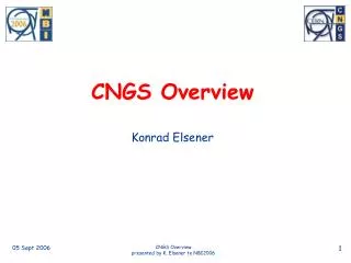
CTF3 photoinjector: A successful collaboration inside JRA “PHIN” – Charge Production with PHoto INjectors University of Milano INFN Frascati M. Divall (“consultant”) CEA (Califes laser)
A huge effort in all the labs involved – a big THANK YOU to everyone (apologies for not mentioning any individual names)
Outline 1. Introduction 2. Overview: Photoinjector for CTF3 3. Recent progress - Installation RF gun - Laser system - Photocathode 4. First electron beam results 5. Summary and Outlook
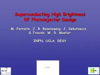
1. Introduction • two photoinjectors at CERN • CALIFES (probe-beam in CLEX) • PHIN (initially on test-bench in CTF2 building, • later to become CTF3 drive beam injector) • - normal conducting RF guns • (inspired by CERN “gun IV”) • - Cs-Te photocathodes • - pulsed UV laser light to produce electrons • differences in the design parameters
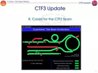
TL2 CLEX CALIFES PHIN DL = Delay Loop (factor 2) CR = Combiner Ring (factor 4) Injector with thermionic gun Drive Beam Accelerator DL CR
Main challenges – CTF3 “PHIN” electron beam (2007) trains of 10 ps pulses at 1.5 GHz (synch. 3 GHz): 1908 pulses in 1272 ns long train (odd/even sub-pulses, 140.7 ns) 2.3 nC per pulse, charge stability 0.25% -> 3.5 A current in the pulse train need 370 nJ UV laser pulse energy... ...for given 3% photocathode quantum efficiency need 15 kW IR laser power in the pulse train repetition rate: 5 Hz
lifetime of the photocathode ? 2. Overview: Photoinjector for CTF3 Main Design Parameters(2007)
vacuum requirements 2x10⁻¹⁰ mbar are a challenge -> 5 ion pumps to further improve the dynamic behavior of pressure: -> 42 holes (d=4mm) between RF gun and NEG chamber courtesy LAL
29 April 2008 – LAL (photo G. Bienvenu)
3a. Recent Progress - Installation 19 June 2008 – CERN (CTF2)
cathode manipulator RF gun diagnostics (emittance meas.+ spectrometer) 7 June 2008 – CERN (CTF2)
400ms amplification window for AMP1 Macro pulse Micro pulses at 1.5 GHz ~667ps; 10W Dt Dt Dt 200ms amplification window for AMP2 Macro pulse UV Green 3b. Recent Progress - Laser 1.5 GHz Nd:YLF Oscillator + Nd:YLF Preamplifier 1047nm 3-pass Nd:YLF amplifier 2 pass Nd:YLF amplifier Optical gate (Pockels cell) PC 4 2 Pulse picker IR
6 5 4 3 2 1 0 0 100 200 300 400 laser beam after 2nd amplifier power [kW] time [ms] N.B. Output Amplifier 1: 3 kW – as specified Output Amplifier2: 6 kW – factor ~2 missing
laser beam after pockels cell (observed with photodiode + scope) 2 ms 667 ps
conversion to UV * measured on laser table – nominal 370 nJ on photocathode
more details on the laser system: Massimo Petrarca today at 15:30 in Room A
3c. Recent Progress - Photocathode Photocathode No. 167 (Cs-Te co-evap.) data taken in DC-gun, 80 kV (-> 8 MV/m) caution: QE not measured since January QE in RF gun tends to be smaller CTF3 photoinj. specification 29 Nov. 2007 Xmas break 9 Jan. 2008
4. First electron beam results ! PRELIMINARY ! - RF conditioning with Cu plug, solenoids OFF - RF conditioning with Cu plug, solenoids ON - RF conditioning with CsTe cathode - 5 Nov.: first beam Timing problem laser vs. RF pulse; Short dark current pulse at the end of rf pulse clearly visible; Intensity roughly equal to a single bunch
- 6 Nov.2008: first electron beam - RF phase adjusted; solenoid currents lowered - optimised first MTV screen beam spot 1.55 m downstream of RF gun: FWHM ~ 5 mm
Beam current – 1.3 ms train (2000 bunches) Beam Position Monitor Sum Signal Faraday Cup laser beam train-to-train UV energy fluctuations in laser room: r.m.s < 3% (500 trains) electron beam train-to-train intensity fluctuations (BPM): r.m.s < 6% (5 minutes)
Phase scan, 50 ns e-beam pulse train 100 deg.
Beam size scan Asymmetry in beam focusing behavior; problem seems to be in horizontal plane, behavior in vertical seems ~ OK Cause? Laser spot asymmetry, alignment, RF-asymmetry, solenoid alignment – to be checked in 2009
Energy measurement, 90 deg. Spectrometer background (dark-current) subtracted Measured nominal energy with small energy spread (calibration to be checked) 5.3 MeV with 27 keV (0.5 %) r.m.s. energy spread
Overview of Results * combination of low QE (old cathode); laser energy not nominal; possibly laser beam not well centred on cathode (diagnostics !)
5. Summary and Outlook • after years of work, and a huge effort by all partners • we had FIRST BEAM in the PHIN CTF3 photoinjector ! • many of the beam parameters measured are already the • nominal parameters + stability is quite good ! • All in all, a GREAT ACHIEVEMENT ! • next run: March 2009 (3 – 4 weeks) (availability of klystron) • workplan: 3 new photocathodes; • improved laser amplifier 2 • improved laser beam diagnostics • improved electron beam diagnostics (screen sensitivity) • -> significant increase of electron intensity • -> detailed emittance measurements
5. Summary and Outlook • later in 2009: • further improvements on laser system • (conversion crystals, amplifiers) • additional work: phase-coding • availability of klystron ? - cf. CTF3 general schedule • A lot of work ahead - • but good prospects to reach much higher intensity in 2009 ! thank you !
4. Status of the photocathodes • Cs – Te photocathodes (theoretically: Cs2Te) • successfully used at CTF2 • progress in recent years: • co-evaporation of Cs and Te onto copper substrate • photocathode production • “in-situ” for CALIFES (cf. CTF2) • in the photoemission lab for PHIN
DC- gun preparation chamber transport carrier 4. Status of photocathodes 4b) Photocathodes for PHIN – Photoemission Laboratory ~ 1.4 m manipulator
4. Status of photocathodes 4b) Photocathodes for PHIN view inside the preparation chamber special features: observe photoelectron production by UV during the evaporation process quartz monitors are calibrated co-evaporation of Te and Cs (masks!)
4. Status of photocathodes 4b) Photocathodes for PHIN on the “arm” inside the transport carrier: up to 4 plugs
4. Status of photocathodes 4b) Photocathodes for PHIN 1992-2002 large number of photocathodes produced (e.g. 58 Cs-Te for CTF2 drive beam) ... work in the lab ... Dec. 2006 photocathode No. 166 (before bake-out of the vacuum system) -> Quantum Efficiency in DC gun 6.2% 2007 tests, bake-out, calibration of thickness monitors, improvements to masks, etc. Nov. 2007 photocathode No. 167 produced under “correct conditions”
Energy measurement, Phase scan Very reasonable behavior
Emittance Emittance= 4.88 mm mrad ‘to good to be true’ Öznür Mete
RF GUN CTF2 , Simulations ref E= 5.4 MeV DE/E= 0.6 % bl = 6.8 ps (FWHM) en = 15.5 mm
Beam parameter summary * photocathode QE < 0.5% (factor 8-11) cathode prod. Dec. 2007 laser micropulse energy < 0.2 mJ (factor 2-3) * NEG not yet activated