Download
1 / 23
230 likes | 335 Views
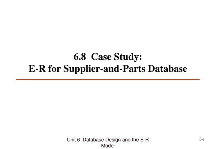
6.8 Case Study: E-R for Supplier-and-Parts Database. < e.g.> Supplier-and-Parts Database. S. SP. S# P# QTY S1 P1 300 S1 P2 200 S1 P3 400 S1 P4 200 S1 P5 100 S1 P6 100 S2 P1 300 S2 P2 400

E N D
Unit 6 Database Design and the E-R Model 6.8 Case Study: E-R for Supplier-and-Parts Database
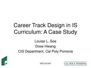
Unit 6 Database Design and the E-R Model <e.g.> Supplier-and-Parts Database S SP S# P# QTY S1 P1 300 S1 P2 200 S1 P3 400 S1 P4 200 S1 P5 100 S1 P6 100 S2 P1 300 S2 P2 400 S3 P2 200 S4 P2 200 S4 P4 300 S4 P5 400 S# SNAME STATUS CITY S1 Smith 20 London S2 Jones 10 Paris S3 Blake 30 Paris S4 Clark 20 London S5 Adams 30 Athens P P# PNAME COLOR WEIGHT CITY P1 Nut Red 12 London P2 Bolt Green 17 Paris P3 Screw Blue 17 Rome P4 Screw Red 14 London P5 Cam Blue 12 Paris P6 Cog Red 19 London Supplier-and-Parts Database • Supplier-and-Parts Database
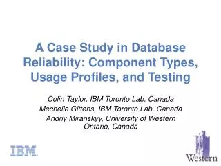
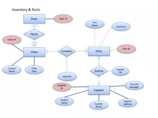
Unit 6 Database Design and the E-R Model ... ... Department Dependent 1 M First MI Last Department_Emp Emp_Dependent Ename M 1 P# Emp# Employee Salary ... M 1 Proj_Work Proj_Mngr M M Project S# ... Sname Qty Qty SPJ M M Supplier Part M Exp M M Imp M Status City SP Part_Struct Qty Entity/Relationship Diagram • Entity : • Property: • Relationship: <e.g> Regular Entity Weak Entity Base Derived Multi Key Composite Weak Regular partial total
Unit 6 Database Design and the E-R Model Semantic Concepts • Entity: a thing which can be distinctly identified. e.g. S, P • Weak Entities: an entity that is existence-dependent on some other entity. e.g. Dependent • Regular Entities: an entity that is not weak. • Property: • Simple or Composite Property • key: unique value • Single or Multi-valued: i.e. repeating data • Missing: unknown or not applicable. • Base or Derived: e.g. "total quantity"
Unit 6 Database Design and the E-R Model Dependent M 1 Employee Semantic Concepts (cont.) • Relationship: association among entities. • participant: the entity participates in a relationship. e.g. Employee, Dependent • degree of relationship: number of participants. • total participant: every instance is used. e.g. Dependent • partial participant: e.g. Employee Note: An E/R relationship can be one-to-one, one-to- many, many-to-one, or many-to-many. Employee Dependent . . . . . . . . E1 E2 E3 E4
Unit 6 Database Design and the E-R Model Employee Programmer Application Programmer System Programmer Semantic Concepts (cont.) • Subtype: Any given entity can be a subtype of other entity. e.g. An example type hierarchy: • Programmer Employee • Application Programmer Programmer
Unit 6 Database Design and the E-R Model ER-Diagram SQL Definition TransferE-R Diagram to SQL Definition (1) Regular Entities Base Relations • e.g. Department DEPT • Employee EMP • Supplier S • Part P • Project J • attributes: properties. • primary key: key property. • <e.g> CREATE TABLE EMP • (EMP# ...... • . • . • . • primary key (EMP#)); • . • . • . (2) Properties attributes • multivalued property: normalized first.
Unit 6 Database Design and the E-R Model P# S# M M P SP S QTY TransferE-R Diagram to SQL Definition (cont.) (3) Many-to-Many RelationshipsBase Relations • <e.g.> Consider • SUPP-PART SP • foreign keys:key attributes of the participant entity. • primary key: • (1) combination of foreign keys, or • (2) introduce a new attribute. • attributes: • primary key foreign keys properties • <e.g.>CREATE TABLE SP • ( S#, ..., • P#, ..., • Qty, ..., • FOREIGN KEY (S#) REFERENCES S • NULL NOT ALLOWED • DELETE OF S RESTRICTED • UPDATE OF S.S# CASCADES • FOREIGN KEY (P#) REFERENCES P • ...... • PRIMARY KEY (S#, P#) ) ID S# P# QTY 1 2 3 ...
Unit 6 Database Design and the E-R Model Department (DEPT) DEPT# 1 DEPT_EMP M Employee (EMP) EMP# DEPT# TransferE-R Diagram to SQL Definition (cont.) (4) Many-to-One or One-to-Many or One-to-One Relationships → 不用給Base-Relation, 但…. e.g. Consider DEPT_EMP(Department_Employee) 1° no any new relation is necessary. 2° Introduce a foreign key in "many" side relation (eg. EMP) that reference the "one" side relation (eg. DEPT). CREATE TABLEEMP ( EMP#, ... DEPT#, ... ...... FOREIGN KEY (DEPT#) REFERENCES DEPT ...... );
Unit 6 Database Design and the E-R Model TransferE-R Diagram to SQL Definition (cont.) (5) Weak Entities Base Relation + Foreign Key • foreign key: key property of its dependent entity • primary key: • (1) combination of foreign key and its own primary key • (2) introduce a new attribute • e.g. CREATE TABLEDEPENDENT • ( EMP#, … • name, • ...... • FOREIGN KEY (EMP#) REFERENCES EMP • NULL NOT ALLOWED • DELETE OF EMP CASCADES • UPDATE OF EMP.EMP# CASCADES • PRIMARY KEY ( EMP#, DEPENDENT_NAME ) ); e.g. EMP# e.g. name name EMP# Dependent M 1 EMP# EMP
Unit 6 Database Design and the E-R Model TransferE-R Diagram to SQL Definition (cont.) (6) Supertypes and SubtypesBase Relation + Foreign Key • <e.g.> CREATE TABLEEMP • ( EMP#, ... • DEPT#, ... • SALARY, ... • ...... • PRIMARY KEY (EMP#), ...); • CREATE TABLEPGMR • ( EMP#, ... • LANG#, ... • SALARY, ... • ...... • PRIMARY KEY (EMP#) • FOREIGN KEY (EMP#) REFERENCES EMP • ......); EMP PGMR
17.7 The Entity/Relationship Model Proposed by Peter Pin-Shan Chen. “The Entity- Relationship Model,” in ACM Trans. on Database System Vol. 1, No. 1, pp.9-36, 1976. E-R Model contains: Semantic Concepts and E/R Diagram.
... ... Department Dependent 1 M First MI Last Department_Emp Emp_Dependent Ename M 1 P# Emp# Employee Salary ... M 1 Proj_Work Proj_Mngr M M Project S# ... Sname Qty Qty SPJ M M Supplier Part M Exp M M Imp M Status City SP Part_Struct Qty Entity/Relationship Diagram • Entity : • Property: • Relationship: <e.g> Regular Entity Weak Entity Base Derived Multi Key Composite Weak Regular partial total
Semantic Concepts • Entity: a thing which can be distinctly identified. e.g. S, P • Weak Entities: an entity that is existence-dependent on some other entity. e.g. Dependent • Regular Entities: an entity that is not weak. • Property: • Simple or Composite Property • key: unique value • Single or Multi-valued: i.e. repeating data • Missing: unknown or not applicable. • Base or Derived: e.g. "total quantity"
Dependent M 1 Employee Semantic Concepts (cont.) • Relationship: association among entities. • participant: the entity participates in a relationship. e.g. Employee, Dependent • degree of relationship: number of participants. • total participant: every instance is used. e.g. Dependent • partial participant: e.g. Employee Note: An E/R relationship can be one-to-one, one-to- many, many-to-one, or many-to-many. Employee Dependent . . . . . . . . E1 E2 E3 E4
Employee Programmer Application Programmer System Programmer Semantic Concepts (cont.) • Subtype: Any given entity can be a subtype of other entity. e.g. An example type hierarchy: • Programmer Employee • Application Programmer Programmer
ER-Diagram SQL Definition TransferE-R Diagram to SQL Definition (1) Regular Entities Base Relations • e.g. Department DEPT • Employee EMP • Supplier S • Part P • Project J • attributes: properties. • primary key: key property. • <e.g> CREATE TABLE EMP • (EMP# ...... • . • . • . • primary key (EMP#)); • . • . • . (2) Properties attributes • multivalued property: normalized first.
P# S# M M P SP S QTY TransferE-R Diagram to SQL Definition (cont.) (3) Many-to-Many RelationshipsBase Relations • <e.g.> Consider • SUPP-PART SP • foreign keys:key attributes of the participant entity. • primary key: • (1) combination of foreign keys, or • (2) introduce a new attribute. • attributes: • primary key foreign keys properties • <e.g.>CREATE TABLE SP • ( S#, ..., • P#, ..., • Qty, ..., • FOREIGN KEY (S#) REFERENCES S • NULL NOT ALLOWED • DELETE OF S RESTRICTED • UPDATE OF S.S# CASCADES • FOREIGN KEY (P#) REFERENCES P • ...... • PRIMARY KEY (S#, P#) ) ID S# P# QTY 1 2 3 ...
Department (DEPT) DEPT# 1 DEPT_EMP M Employee (EMP) EMP# DEPT# TransferE-R Diagram to SQL Definition (cont.) (4) Many-to-One or One-to-Many or One-to-One Relationships → 不用給Base-Relation, 但…. e.g. Consider DEPT_EMP(Department_Employee) 1° no any new relation is necessary. 2° Introduce a foreign key in "many" side relation (eg. EMP) that reference the "one" side relation (eg. DEPT). CREATE TABLEEMP ( EMP#, ... DEPT#, ... ...... FOREIGN KEY (DEPT#) REFERENCES DEPT ...... );
TransferE-R Diagram to SQL Definition (cont.) (5) Weak Entities Base Relation + Foreign Key • foreign key: key property of its dependent entity • primary key: • (1) combination of foreign key and its own primary key • (2) introduce a new attribute • e.g. CREATE TABLEDEPENDENT • ( EMP#, … • name, • ...... • FOREIGN KEY (EMP#) REFERENCES EMP • NULL NOT ALLOWED • DELETE OF EMP CASCADES • UPDATE OF EMP.EMP# CASCADES • PRIMARY KEY ( EMP#, DEPENDENT_NAME ) ); e.g. EMP# e.g. name name EMP# Dependent M 1 EMP# EMP
TransferE-R Diagram to SQL Definition (cont.) (6) Supertypes and SubtypesBase Relation + Foreign Key • <e.g.> CREATE TABLEEMP • ( EMP#, ... • DEPT#, ... • SALARY, ... • ...... • PRIMARY KEY (EMP#), ...); • CREATE TABLEPGMR • ( EMP#, ... • LANG#, ... • SALARY, ... • ...... • PRIMARY KEY (EMP#) • FOREIGN KEY (EMP#) REFERENCES EMP • ......); EMP PGMR
Home Work: Term Project • Design and implementation an useful, complete, and “real” database system. • Steps: • Take any data you are familiar with. (from your work or ?) • System Analysis represented by flow chart • By using the E-R model to analysis and describe your data. • Design logical database, user interface, and more • Design the database system as “complete and real” as possible. • Due: • Demo and • A Comprehensive Report